
Airbag system

Active Publication Date: 2009-12-10
TOYODA GOSEI CO LTD
View PDF4 Cites 9 Cited by
  • Summary
  • Abstract
  • Description
  • Claims
  • Application Information

AI Technical Summary

Benefits of technology

[0009]The present invention has been made in order to solve the above-mentioned problems, and an object thereof is to provide an airbag system that enables a shift movement of the airbag body in both upper and lower directions with respect to a passenger and can easily secure the distance of the shift movement large, and can thus improve an effect of suppressing a load of the airbag on the passenger.
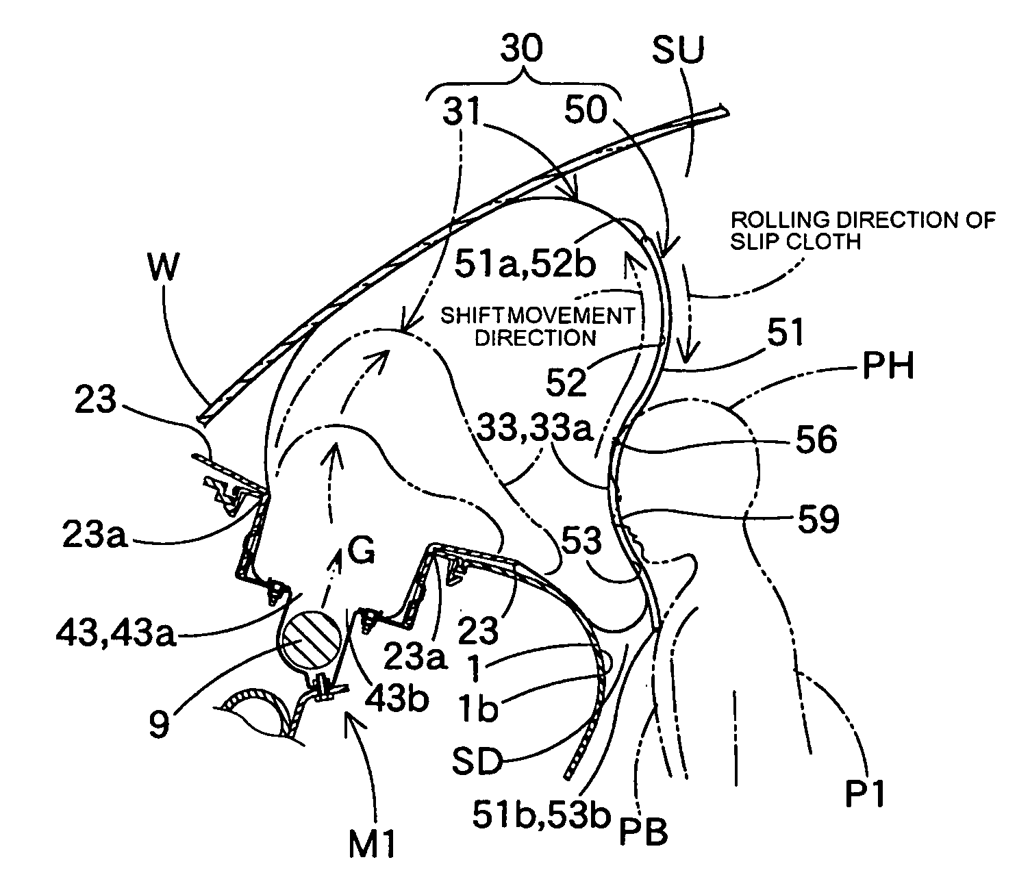
[0017]In the airbag system according to the present invention, during actuation, when the airbag contacts a passenger in the course of deploying and inflating, the passenger-side wall portion of the airbag body does not directly contact the passenger, but the front panel portion of the slip cloth contacts the passenger. Then, when the passenger-side wall portion attempts to shift and move upward and downward with respect to the passenger, a contact portion being in contact with the passenger in the front panel portion is integrated by frictional resistance or the like with the passenger and does not move, however, the upper back panel portion and the lower back panel portion at the back side of the contact portion can shift to move upward and downward with respect to the front panel portion. In other words, when the passenger-side wall portion attempts to shift and move upward and downward with respect to the passenger, the slip cloth moves a joint portion of the upper back panel portion and the lower back panel portion to the passenger-side wall portion upward and downward along with the passenger-side wall portion and shifts and moves the joint portion with respect to the contact portion of the front panel portion with the passenger, and as a result, the passenger-side wall portion can shift to move upward and downward with respect to the passenger without applying a load. In addition, the passenger-side wall portion, even if this contacts the passenger with the slip cloth intervening in the course of inflating, shifts to move upward and downward with respect to the passenger, and the airbag body smoothly completes inflation. Therefore, it becomes possible to satisfactorily protect the passenger by the airbag body that has completed inflation, and for example, even if the passenger hits at a position biased upward and downward with respect to the passenger-side wall portion with the slip cloth intervening at the initial contact, the airbag body smoothly completes inflation, and the passenger is received with excellent cushioning characteristics by the passenger-side wall portion that has completed inflation.
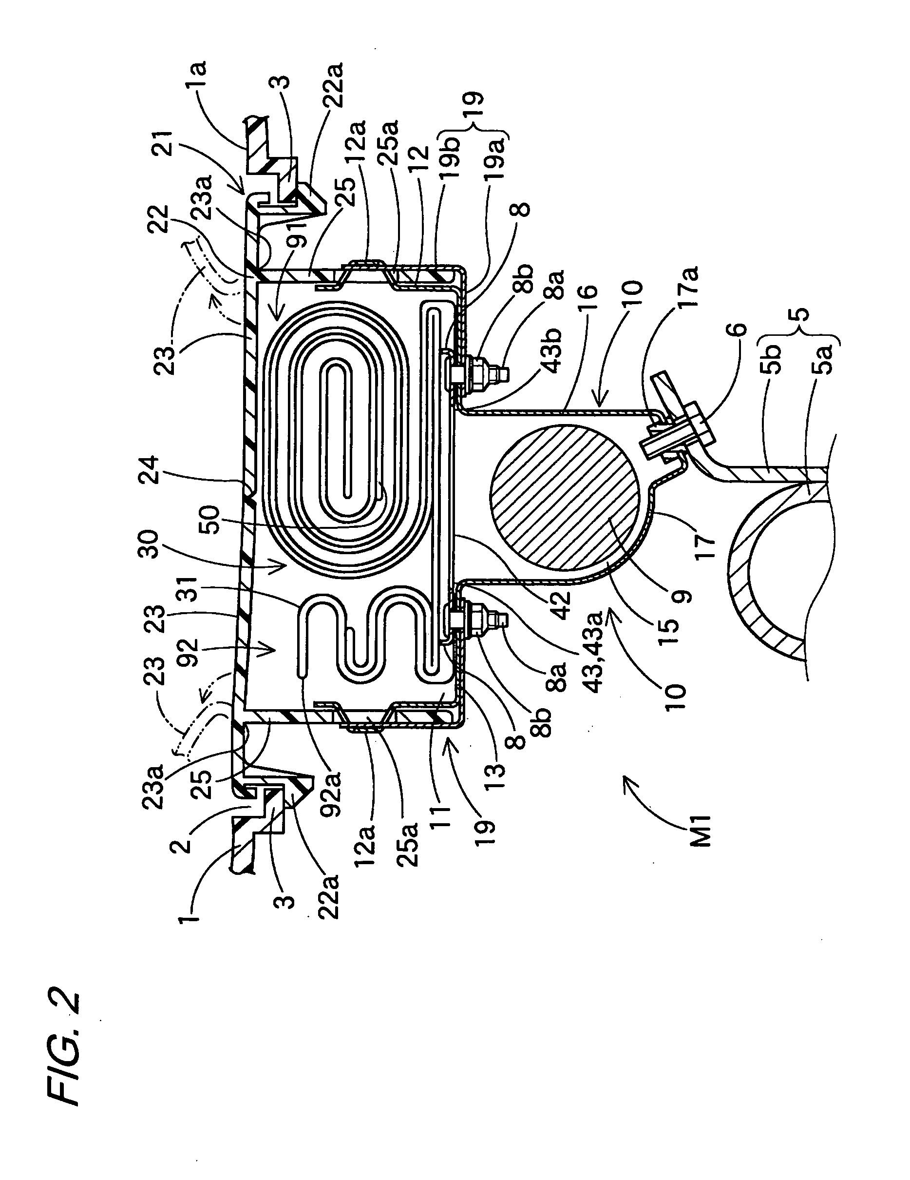
[0018]In addition, the slip cloth is, in a loop shape where the lower end of the upper back panel portion and the upper end of the lower back panel portion are mutually approximated, connected to the passenger-side wall portion. Therefore, while the front panel portion is made to contact with the passenger, for example, when the passenger-side wall portion attempts to shift and move upward, the slip cloth rolls on the surface of the passenger-side wall portion so that the initial lower end of the front panel portion enters an area of the initial lower back panel portion at the back side and the initial upper end of the upper back panel portion enters an area of the initial front panel portion at the front side. Conversely, when the passenger-side wall portion attempts to shift and move downward, the slip cloth rolls on the surface of the passenger-side wall portion so that the initial upper end of the front panel portion enters the area of the initial upper back panel portion at the back side and the initial lower end of the lower back panel portion enters the area of the initial front panel portion at the front side. In addition, the distance by which the slip cloth can roll upward and downward equals a distance until the joint portion of the upper back panel portion and the lower back panel portion to the passenger-side wall portion is arranged from the uppermost end position to the lowermost end position of the loop-shaped slip cloth, and the slip cloth can roll a distance of about ½ of the perimeter of the slip cloth between the passenger-side wall portion and the passenger, so that the distance of shift movement in the upper and lower direction of the passenger-side wall portion with respect to the passenger can be easily secured large in proportion to increasing the perimeter of the slip cloth.
[0019]Accordingly, the airbag system according to the present invention enables a shift movement of the airbag body in both upper and lower directions with respect to a passenger and can easily secure the distance of the shift movement large, and can thus improve an effect of suppressing a load of the airbag on the passenger.
[0022]In the airbag system thus constructed, the width dimensions in the left and right direction of the slip cloth are made substantially identical across the circumferential direction, and the upper and lower back panel portions are joined to the passenger-side wall portion across substantially the entire area in the left and right direction, and thus when folding up the airbag in assembly of the airbag system, assembling work can be easily performed without the slip cloth shifting in the left and right direction with respect to the passenger-side wall portion.
[0026]Accordingly, when the airbag in the course of deploying and inflating contacts the passenger, the passenger-side wall portion is capable of a shift movement not only in both upper and lower directions but also in both left and right directions, with respect to the passenger. In addition, even if the passenger hits the passenger-side wall portion of the airbag body in the course of inflating in a biased manner not only upward and leftward but also leftward and rightward with respect to the passenger-side wall portion of the airbag body in the course of inflating via the slip cloth, the airbag body smoothly completes inflation, and the passenger is received with excellent cushioning characteristics by the passenger-side wall portion that has completed inflation.

Problems solved by technology

Therefore, in the airbag system where one of the upper end or the lower end of the patch is fixed to the passenger-side wall portion, the direction in which the patch can move with respect to the passenger-side wall portion is limited to one direction of the fixed side, so that depending on an upward or downward moving direction of the passenger-side wall portion with respect to the passenger, it has been difficult to appropriately suppress a load of the airbag to be applied to the passenger.

Method used


Image

  • Airbag system
  • Airbag system
  • Airbag system

Examples


first embodiment

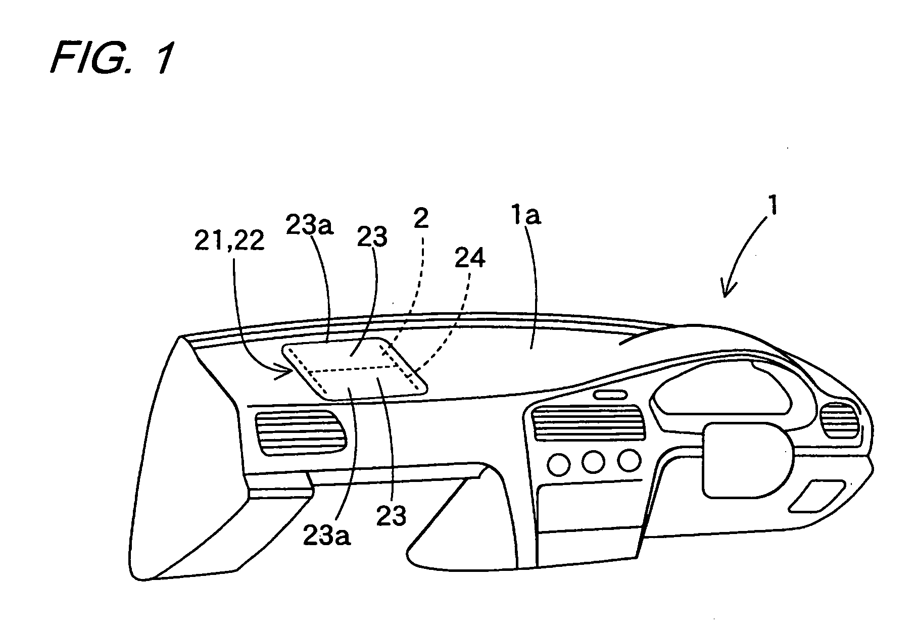
[0095]As has been described above, in the airbag system M1 of the first embodiment, a shift movement of the airbag body 31 in both upper and lower directions with respect to the passenger P1, P2 is enabled, and the distance of the shift movement can be easily secured large, so that the effect of suppressing a load of the airbag 30 on the passenger P1, P2 can be improved.

[0096]Further, in the airbag system M1 of the first embodiment, for the slip cloth 50, the width dimensions D1, D2, and D3 in the left and right direction of the front panel portion 51 and the upper and lower back panel portions 52 and 53 are made substantially identical across the circumferential direction, and the upper and lower back panel portions 52 and 53 are joined to the passenger-side wall portion 33 across substantially the entire area in the left and right direction, and thus when folding up the airbag 30 in assembly of the airbag system M1, assembling work can be easily performed without the slip cloth 50...

second embodiment

[0102]An airbag system M2 (see FIGS. 19A and 19B) of the second embodiment shown in FIG. 14 to FIG. 20B, the slip cloth 60 further includes, besides a front panel portion 61, an upper back panel portion 62, and a lower back panel portion 63, a left back panel portion 64 arranged on the passenger-side wall portion 33 at the back side of the front panel portion 61 and extending rightward from a left end 61c of the front panel portion 61 and a right back panel portion 65 arranged on the passenger-side wall portion 33 at the back side of the front panel portion 61 and extending leftward from a right end 61d of the front panel portion 61.

[0103]The front panel portion 61 and the respective back panel portions 62, 63, 64, and 65 are, as shown by alternate long and two short dashed lines in FIG. 15, formed of one substantially regular square-shaped slip cloth raw material 86 in such a manner as to have diagonal lines along the upper and lower direction and the left and right direction of th...


PUM


Abstract

An airbag system includes an airbag, and the airbag includes an airbag body having a passenger-side wall portion that is arranged at a passenger side when having completed deploying and inflating, and a slip cloth that is disposed at an outer surface side of the passenger-side wall portion. The slip cloth formed in a loop shape an axial direction of which is in a left and right direction includes: a front panel portion arranged at a passenger side; an upper back panel portion extending downward from an upper end of the front panel portion; and a lower back panel portion extending upward from a lower end of the front panel portion, and a lower end of the upper back panel portion and an upper end of the lower back panel portion are mutually approximated, and joined to the passenger-side wall portion.

Description

BACKGROUND OF THE INVENTION[0001]1. Field of the Invention[0002]The present invention relates to an airbag system, and more particularly, to an airbag system that suppresses a load on a passenger when an airbag in the course of deploying and inflating contacts the passenger.[0003]2. Related Art[0004]Conventionally, as an airbag system that suppresses a load on a passenger when an airbag in the course of deploying and inflating contacts the passenger, there has been known one for which a soft outer cover movable with respect to an airbag body is disposed outside the airbag body so that the passenger's face slides on the surface of the airbag body with the soft outer cover to prevent an abrasion (see JP S62-43056U, for example).[0005]Moreover, as the airbag system, there has been known an airbag system including an airbag having an airbag body and a patch, in which the patch is disposed so as to cover at least a surface of a passenger-side wall portion, and is capable of relatively mo...

Claims


Application Information

Patent Timeline
IPC IPC(8): B60R21/16
CPCB60R21/205B60R21/231B60R2021/23386B60R21/237B60R21/2338
Inventor KOYAMA, TORUGOTO, YOSHIAKIBITO, KAZUAKI
Owner TOYODA GOSEI CO LTD
Learn More