
Thermal cycler with protection from atmospheric moisture

a technology of atmospheric moisture and cycler, which is applied in the field of laboratory equipment, can solve the problems of affecting the mold mold, and condensation on the module surface, and achieves the effect of facilitating the molding of parts

Active Publication Date: 2006-05-30
BIO RAD LAB INC
View PDF20 Cites 42 Cited by
  • Summary
  • Abstract
  • Description
  • Claims
  • Application Information

AI Technical Summary

Benefits of technology

This configuration enhances the thermal efficiency and reliability of thermoelectric modules by preventing moisture intrusion and ensuring unobstructed airflow around heat sink fins, thereby improving temperature control precision and consistency during thermal cycling processes.

Problems solved by technology

While the modules are highly effective and versatile, their efficiency can be compromised by a variety of factors in the construction of the cycler.
The temperature changes can cause condensation on the module surfaces, for example, and the clamping apparatus that assures that the components are in full thermal contact can interfere with the heat sink fins.

Method used


Image

  • Thermal cycler with protection from atmospheric moisture
  • Thermal cycler with protection from atmospheric moisture
  • Thermal cycler with protection from atmospheric moisture

Examples


Embodiment Construction

[0014]Each of the several different aspects of the present invention is susceptible to a wide range of variation in terms of the configurations of each component, the arrangements of the components in the assembly, the particular instrument or apparatus in which they are incorporated, and the function that the instrument is designed to perform. A detailed review of one particular embodiment however will provide an understanding of the function and operation of the invention in each of its many embodiments. The figures hereto depict a thermal cycler for a PCR instrument as one such embodiment.

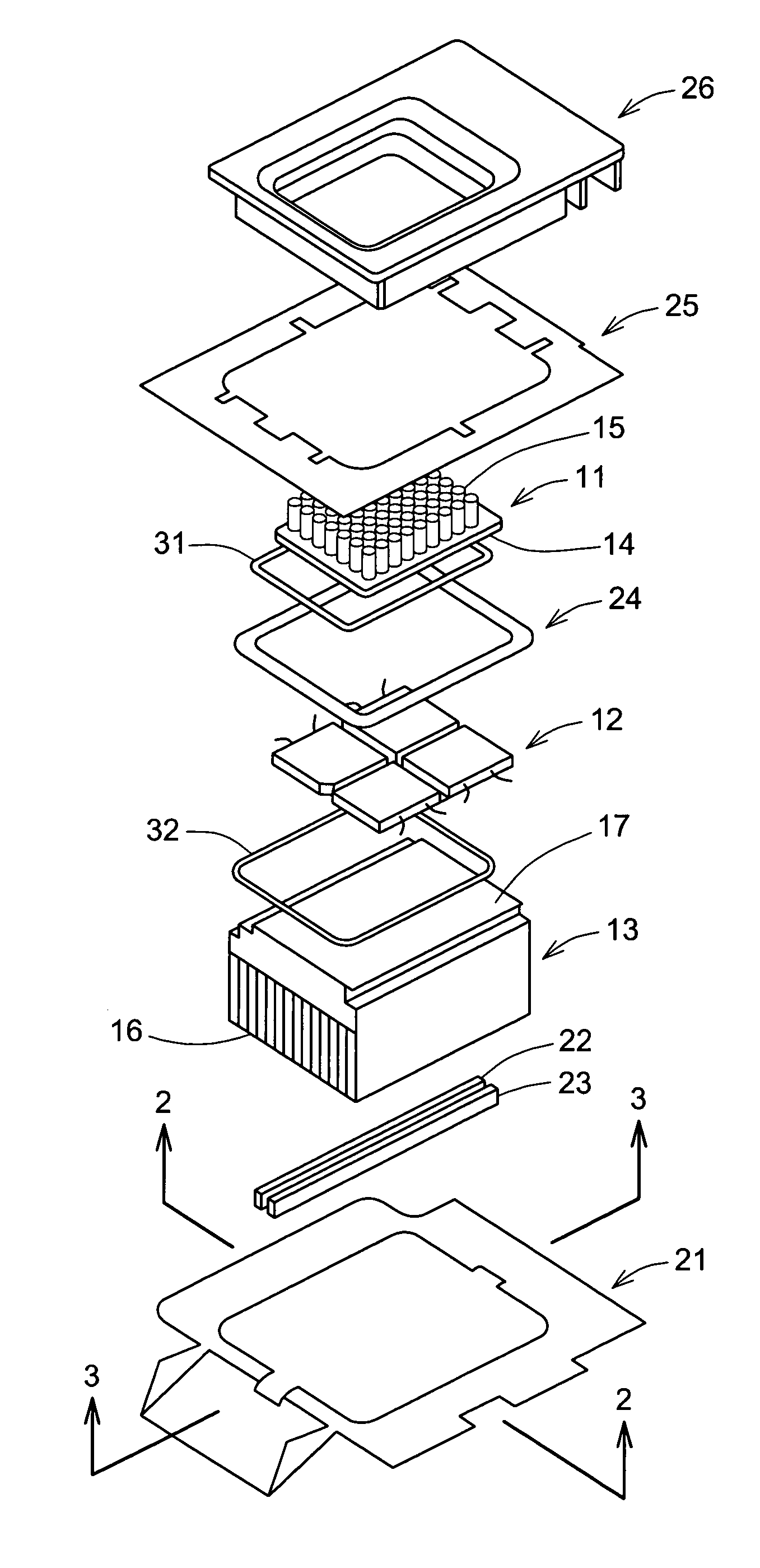
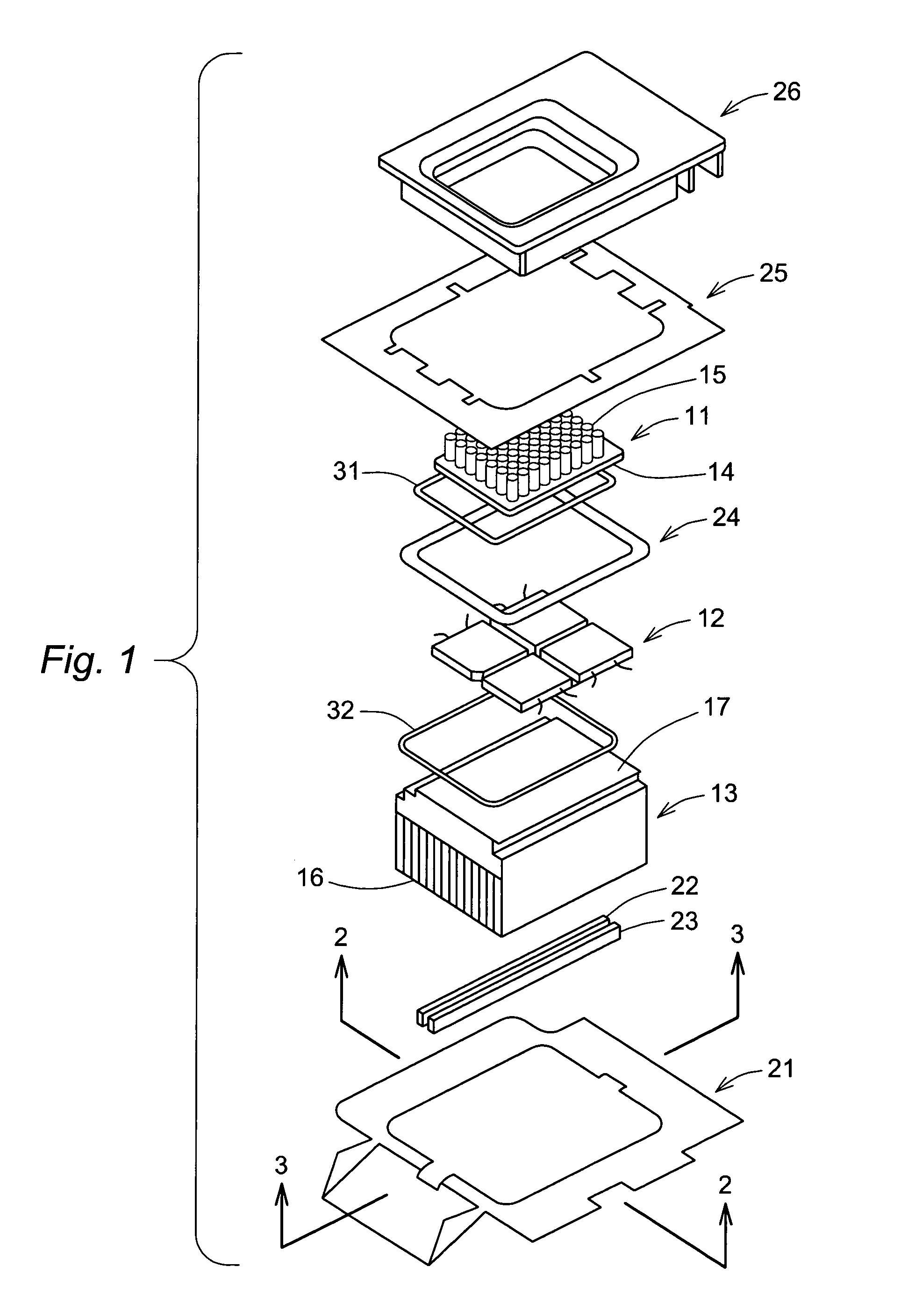
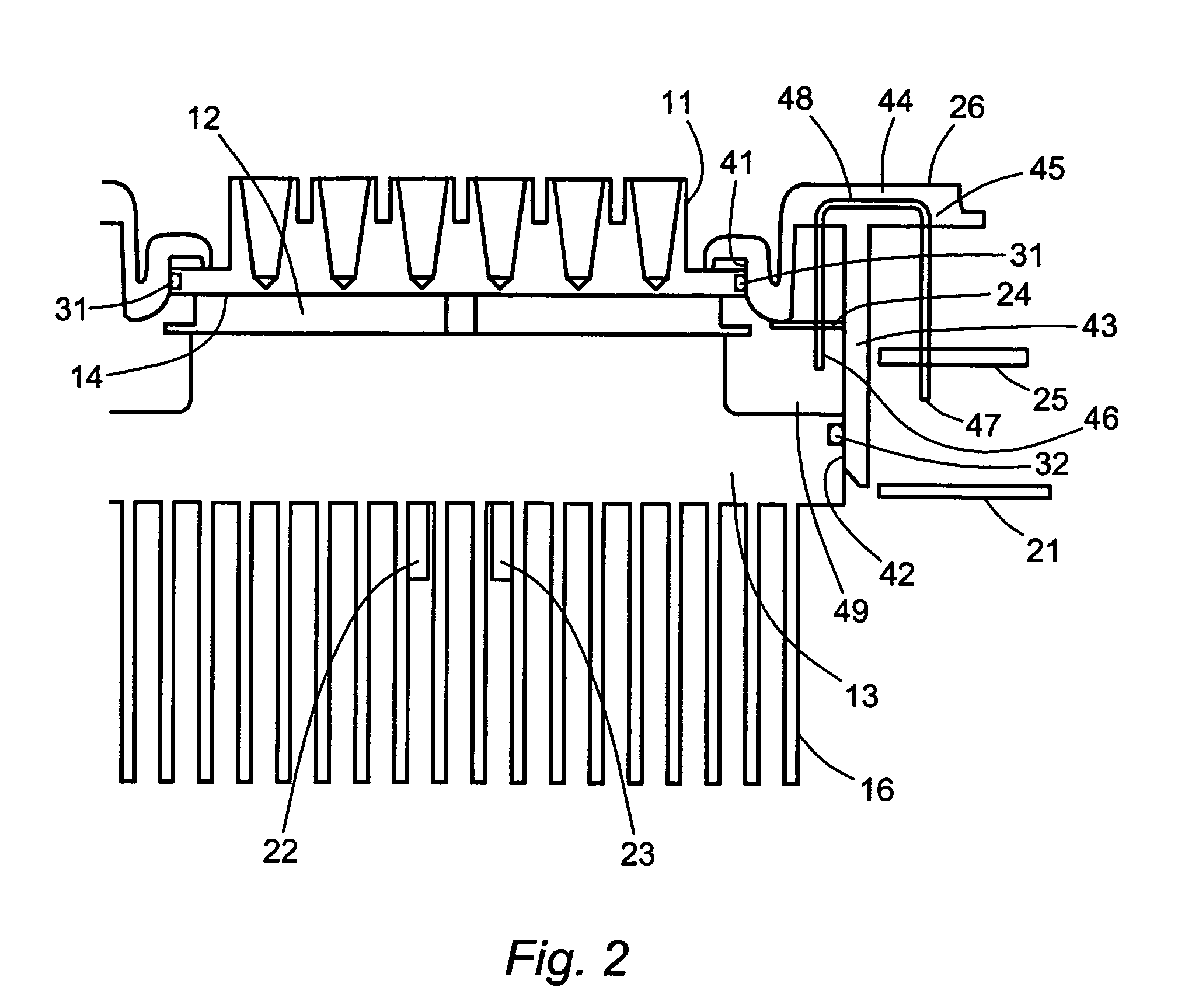
[0015]The components shown in the exploded perspective view of FIG. 1 include a sample block 11, thermoelectric modules 12, and a finned heat sink 13. These three components are shaped to allow them to be stacked in a configuration that places the broad faces on the upper and lower sides of the thermoelectric modules in thermal contact with the sample block and the heat sink, respectively. The t...


PUM


Abstract

Localized temperature control in a thermal cycler is achieved by thermoelectric modules that are protected from exposure to atmospheric moisture by a pair of loop-shaped gaskets that seal off an enclosure formed by the sample block, the heat sink, and a support frame to which the components are secured. The heat sink is a block with a plurality of fins and is secured to the thermoelectric modules by one or more clamping bars that fit between the fins and are arranged to eliminate interference with the fin geometry and with the functional surface area of the fins. Electric leads are embedded in a molded retainer element, each lead being in the shape of a “U” with two exposed legs joined by a bar at one end, one of the leads extending into the region sealed from the atmosphere and the other extending outside the region.

Description

BACKGROUND OF THE INVENTION[0001]1. Field of the Invention[0002]This invention resides in the field of laboratory apparatus for performing procedures that require simultaneous temperature control in a multitude of samples in a multi-receptacle sample block. In particular, this invention addresses concerns arising with the use of thermoelectric modules for temperature modulation and control.[0003]2. Description of the Prior Art[0004]The polymerase chain reaction (PCR) is one of many examples of chemical processes that require precise temperature control of reaction mixtures with rapid temperature changes between different stages of the procedure. PCR is a process for amplifying DNA, i.e., producing multiple copies of a DNA sequence from a single copy. PCR is typically performed in instruments that provide reagent transfer, temperature control, and optical detection in a multitude of reaction vessels such as wells, tubes, or capillaries. The process includes a sequence of stages that ...

Claims


Application Information

Patent Timeline
Patent Type & Authority Patents(United States)
IPC IPC(8): F25B21/02
CPCF25B21/04F25B2321/023B01L7/52B01L2300/1822B01L3/50851B01L2200/025B01L2200/0689B01L2300/0829B01L2300/0838B01L2300/1894
Inventor COHEN, DAVID A.BANERJI, SUNANDDENNINGER, MICHAEL J.
Owner BIO RAD LAB INC
Learn More