
Peristaltic irrigation pump system

a pump system and pump technology, applied in the direction of positive displacement liquid engine, enemata/irrigator, other medical devices, etc., can solve the problems of device complex, device is relatively complex, and requires more manipulation of the cass

Active Publication Date: 2005-05-05
LINVATEC
View PDF2 Cites 42 Cited by
  • Summary
  • Abstract
  • Description
  • Claims
  • Application Information

AI Technical Summary

Benefits of technology

[0020] These and other objects are accomplished by the preferred embodiment of the system disclosed herein which comprises a tubing system for use with a pump having a peristaltic roller assembly. The roller assembly is rotatable in a plane parallel to the front panel of the pump housing and perpendicular to an axis of rotation. While the preferred embodiment is described in terms of a vertical plane of rotation and a horizontal axis, it will be understood that any orientation is feasible. The system comprises a flexible tubing set including a cassette for facilitating the proper positioning of a portion of the tubing set adjacent the pump roller assembly. The cassette comprises a frame which holds a portion of the flexible tube in a loop configuration and enables the loop to be connected to appropriate inflow and outflow tubes. The cassette frame is provided with a pair of tube supports at points spaced apart a predetermined distance and supports a feedback channel in fluid communication with the inflow and outflow tubes. The feedback channel is provided with a pressure transducer designed to operate with a one-sided pressure sensor on the front panel. The feedback channel enables continuous motion of the peristaltic roller assembly and provides a pressure relief mechanism.

Problems solved by technology

This device is relatively complex and requires more manipulation of the cassette than is desired in certain surgical applications.
The device is relatively complex.
However, one can reasonably expect it to be relatively complex since the articulating arms must both be moved simultaneously.
One disadvantage of this arrangement is that if a user inadvertently connects a liquid supply to the tube set (i.e. “spikes the bags”) before inserting the cushion into the slot, the pressure of the liquid will have expanded the membranes to a point where the cushion will not fit into the slot.

Method used


Image

  • Peristaltic irrigation pump system
  • Peristaltic irrigation pump system
  • Peristaltic irrigation pump system

Examples


Embodiment Construction

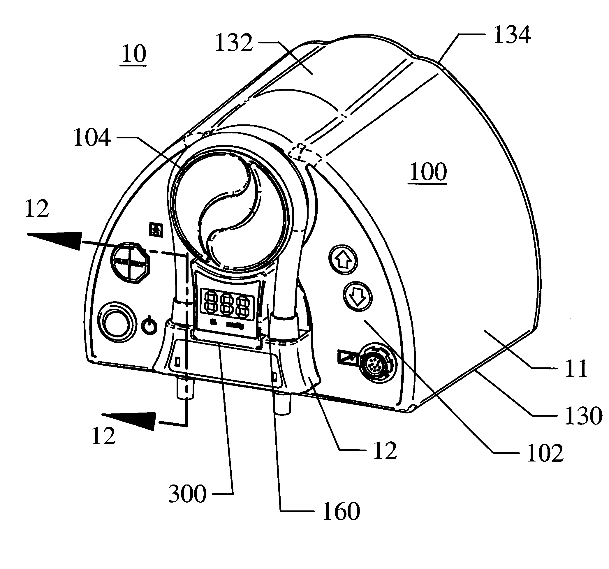
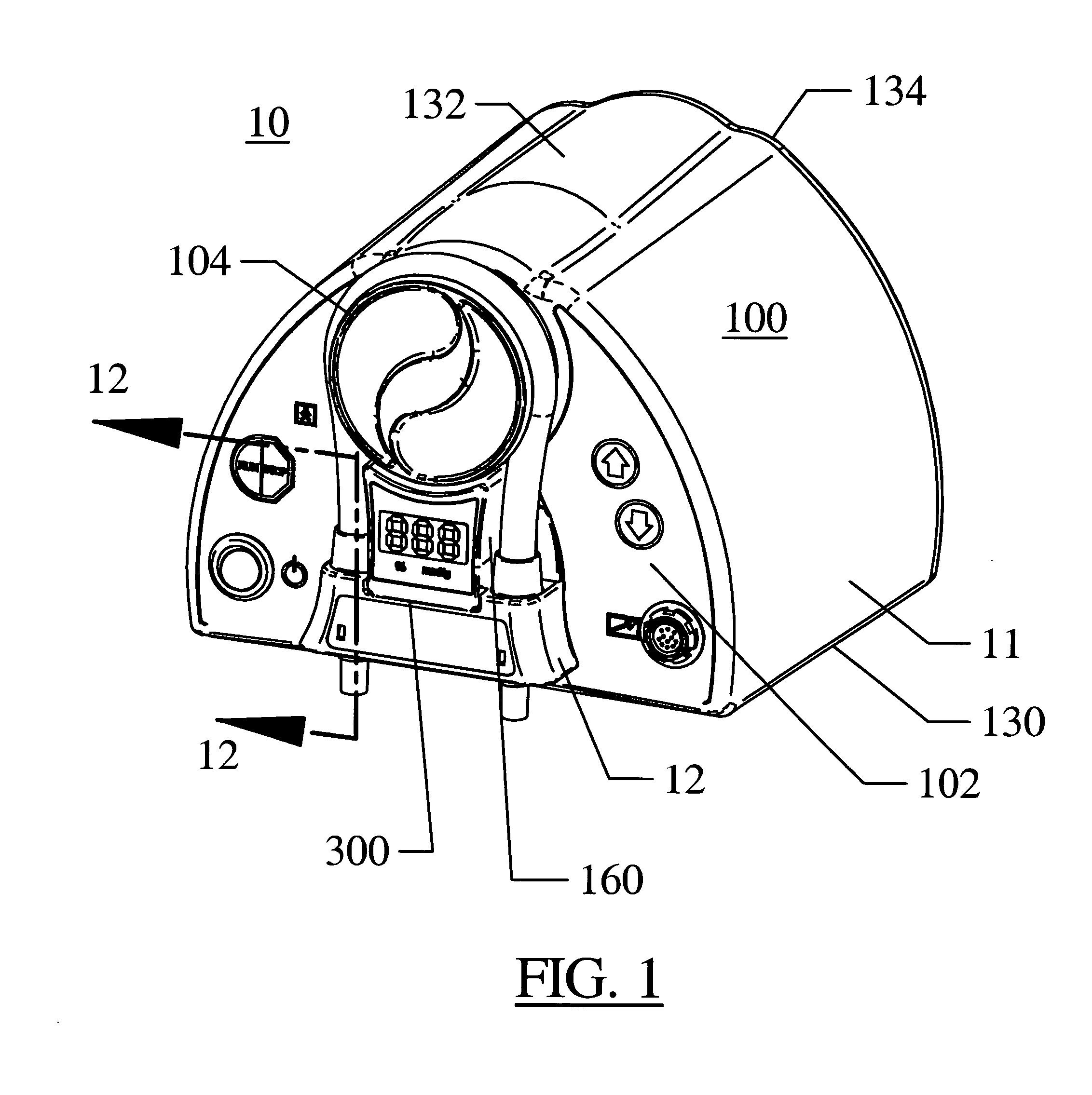
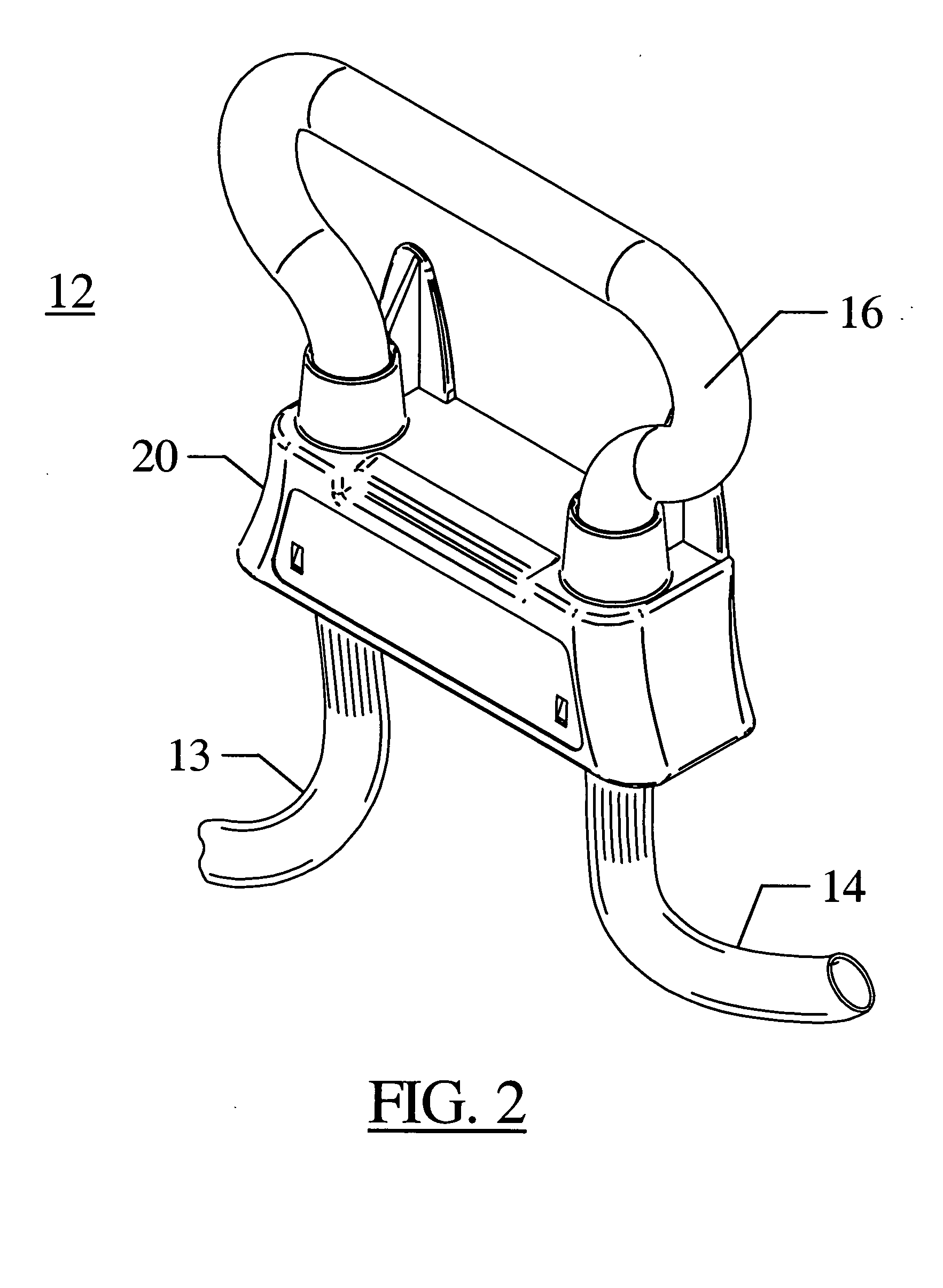
[0044] Referring now to FIGS. 1 and 2 there is shown a peristaltic irrigation pump system 10 constructed in accordance with the principles of this invention, comprising pump 11 and tubing set 12. In the preferred embodiment, pump 11 is a peristaltic pump although it will be understood that the invention may be adapted to any positive displacement pump.

[0045] As seen in FIGS. 2-11, tubing set 12 comprises an inlet tube assembly 13, an outlet tube assembly 14 and an intermediate looped tube 16, all situated and held by tubing cassette 20. All tubes are preferably resilient and flexible and formed of suitable biocompatible material. As used herein, the term “tubing cassette” broadly means a device for holding at least a portion of the tube, which device is manipulated to facilitate engagement of the tubing set with the pump. Inlet tube assembly 13 may be provided with an appropriate connector (not shown) at its proximal end in order to enable the tube assembly to be connected to a sui...


PUM


Abstract

A peristaltic pump tubing system for use with a positive displacement pump such as a peristaltic pump roller assembly in a surgical procedure. The system comprises a uniquely shaped disposable tubing cassette for retaining the tubing to be used during the surgical procedure and a uniquely shaped cassette receiving station situated adjacent the peristaltic pump roller assembly. The cassette comprises an open backed frame for holding a flexible tube in a loop shape for engagement with the peristaltic rollers. The frame supports a one-sided pressure transducer to indicate the pressure within the flexible tube. The cassette receiving station includes a sensor for engaging the one-sided pressure transducer and is situated adjacent the rollers of the peristaltic pump on the pump housing. A retaining bracket cooperates with the inherent resiliency of the tubing loop to hold the cassette tubing in place against the rollers. The system incorporates a feedback control loop which provides a continuous visible motion that indicates to a user that the system is operating.

Description

BACKGROUND OF THE INVENTION [0001] 1. Field of the Invention [0002] The invention relates generally to peristaltic irrigation and distension pumps and tubing sets for use therewith. More particularly, the invention relates to an irrigation and distension pump system for surgical use, the system utilizing a tube set having a tubing cassette which holds a looped tube adjacent peristaltic rollers. [0003] 2. Description of the Prior Art [0004] Powered pumps are frequently used in medical and surgical applications in order to pump various fluids during surgical procedures. The fluids are conveyed from a fluid source to a patient and ultimately to a fluid drain via a pump and various inflow and outflow tubes which pass fluid appropriately. Numerous system designs are known by which the tubing used with the pumps may be configured into surgical tube sets adapted for various applications (arthroscopy, laparoscopy, irrigation, etc.). The tube sets may be coded to identify the procedure for w...

Claims


Application Information

Patent Timeline
IPC IPC(8): A61M3/02F04B43/12
CPCA61M3/0258F04B43/1253A61M2205/12A61M3/0216A61M3/022A61M3/0208A61M3/0201A61M3/0202
Inventor BLIGHT, DAVID D.STUBKJAER, ERIC N.FRITZ, JOSEPH A.
Owner LINVATEC
Learn More