Electronic device

a technology of electronic devices and portable terminals, applied in the direction of electrical apparatus construction details, safety/protection circuits, transportation and packaging, etc., can solve the problem of destroying the inner electronic circuit of the portable terminal

Active Publication Date: 2008-08-21
SEIKO EPSON CORP +1
View PDF11 Cites 42 Cited by
  • Summary
  • Abstract
  • Description
  • Claims
  • Application Information

AI Technical Summary

Benefits of technology

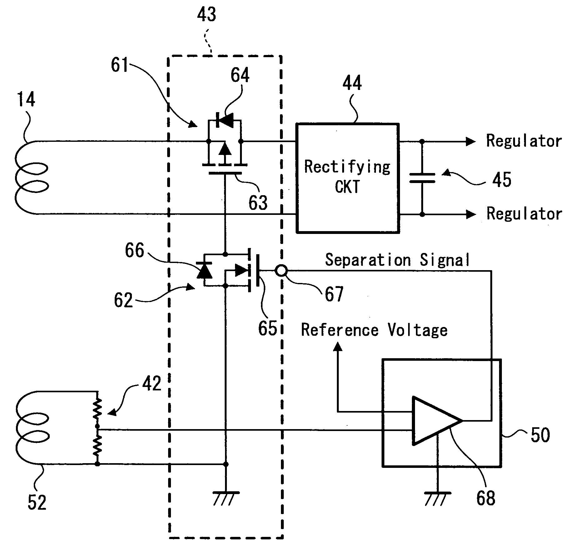
[0020]According to the embodiment of the present invention, an electrical connection between the electric conductor and the electronic circuit is broken when the loop-shaped electric conductor outputs a voltage not smaller than a reference voltage. Accordingly, if the electronic device is subjected to a strong magnetic field or

Problems solved by technology

In such a case, a voltage as high as several hundreds volts is generated from the secondary

Method used


Image

  • Electronic device
  • Electronic device
  • Electronic device

Examples


Embodiment Construction

[0029]Hereinafter, an embodiment of the present invention will be described with reference to the attached drawings.

[0030]In this embodiment, for example, a mobile phone unit, on which a noncontact power-transmission coil formed of a spiral planar coil is mounted, is provided as an example of an electronic device including at least a loop-shaped electric conductor that generates electric power by electromagnetic induction. In addition, as an example of a battery charger for the mobile phone unit, a cradle is provided. Needless to say, any content described herein is only provided as an example and the present invention is thus not limited to such an example.

[0031][General Configurations of Cradle and Mobile Phone Unit and Their Basic Actions in Charging]

[0032]FIG. 3 is a diagram that schematically illustrates the configuration of principal parts of a mobile phone unit 2 and the configuration of principal parts of a cradle 1, which are related to noncontact power transmission.

[0033]T...


PUM


Abstract

An electronic device having at least a loop-shaped electric conductor generating electric power by electromagnetic induction is provided. The electronic device includes a voltage-detecting unit, a voltage-comparing unit and a separating unit. The voltage-detecting unit is configured to detect a voltage generated in the electric conductor by the electromagnetic induction. The voltage-comparing unit is configured to make a comparison between the voltage detected by the voltage-detecting unit and a predetermined reference voltage and determining whether the voltage detected by the voltage-detecting unit exceeds the predetermined reference voltage. The separating unit is configured to break an electric connection between the electronic conductor and an electronic circuit connecting to the electric conductor when the voltage-comparing unit determines that the voltage detected by the voltage-detecting unit exceeds the predetermined reference voltage.

Description

CROSS-REFERENCES TO RELATED APPLICATIONS[0001]The present invention contains subject matter related to Japanese Patent Application JP 2007-039183, filed in the Japanese Patent Office on Feb. 20, 2007, the entire contents of which are incorporated herein by reference.BACKGROUND OF THE INVENTION[0002]1. Field of the Invention[0003]The present invention relates to an electronic device including at least a loop-shaped electric conductor generating electric power by electromagnetic induction.[0004]2. Description of the Related Art[0005]For example, a system for transmitting charge power for charging a rechargeable battery incorporated in a portable terminal using electromagnetic induction with a noncontact power-transmission coil has been known.[0006]In addition, Japanese Unexamined Patent Application Publication No. H11-187582 (FIG. 1 and FIG. 4) discloses a technology for stabilizing a secondary output voltage as follows. In a system for carrying out electric-power transmission by elec...

Claims


Application Information

Patent Timeline
IPC IPC(8): H02J7/04H01F38/00H02J7/00
CPCH01F38/14H02J7/345H02J7/025H02J7/0031H02J50/10H02J7/00308
Inventor KATO, HIROSHISUZUKI, KUNIHARUSUZUKI, KATSUYAYAMAZAKI, MANABUONISHI, KOTAYODA, KENTARO
Owner SEIKO EPSON CORP
Why Eureka
Try Eureka