
Automobile Axle

a technology of automobile axles and shock absorbers, which is applied in the manufacture of wheel components, road vehicles, vehicle components, etc., can solve the problems of loss of control, device insufficient absorption of horizontal stresses, and unsatisfactory accelerated tire wear, so as to reduce premature tire wear

Inactive Publication Date: 2009-12-10
BROOKS MARK
View PDF18 Cites 8 Cited by
  • Summary
  • Abstract
  • Description
  • Claims
  • Application Information

AI Technical Summary

Benefits of technology

[0006]The force-absorbing member includes at least one of a spring, a pneumatic damper, a hydraulic damper, and a permanently-deformable solid. The force-absorbing member is positioned to bias the splined shaft outwardly and to absorb horizontal forces imparted upon the splined shaft, such as those from the wind, vehicle cornering, or side impact. The vehicle axle may also include a safety pin that is biased to prevent further movement of the splined shaft relative to the main axle if the shaft is moved past a predetermined point. In other words, the safety pin prevents automatic return of the shaft to its unbiased configuration after an accident.
[0009]Still another object of this invention is to have a vehicle axle, as aforesaid, that prevents recoil of the splined shaft in case of a side collision.
[0010]Yet another object of this invention is to have a vehicle axle, as aforesaid, that reduces premature tire wear when a vehicle rounds a corner.

Problems solved by technology

This may lead to undesirable accelerated tire wear.
If the force is great enough, the tires may begin to slip on the pavement, resulting in a loss of control.
Although assumably effective for their intended purposes, the existing devices do not adequately absorb horizontal stresses such that tire wear is reduced and the damage from side impact collisions is significantly reduced.

Method used


Image

  • Automobile Axle
  • Automobile Axle
  • Automobile Axle

Examples


Embodiment Construction

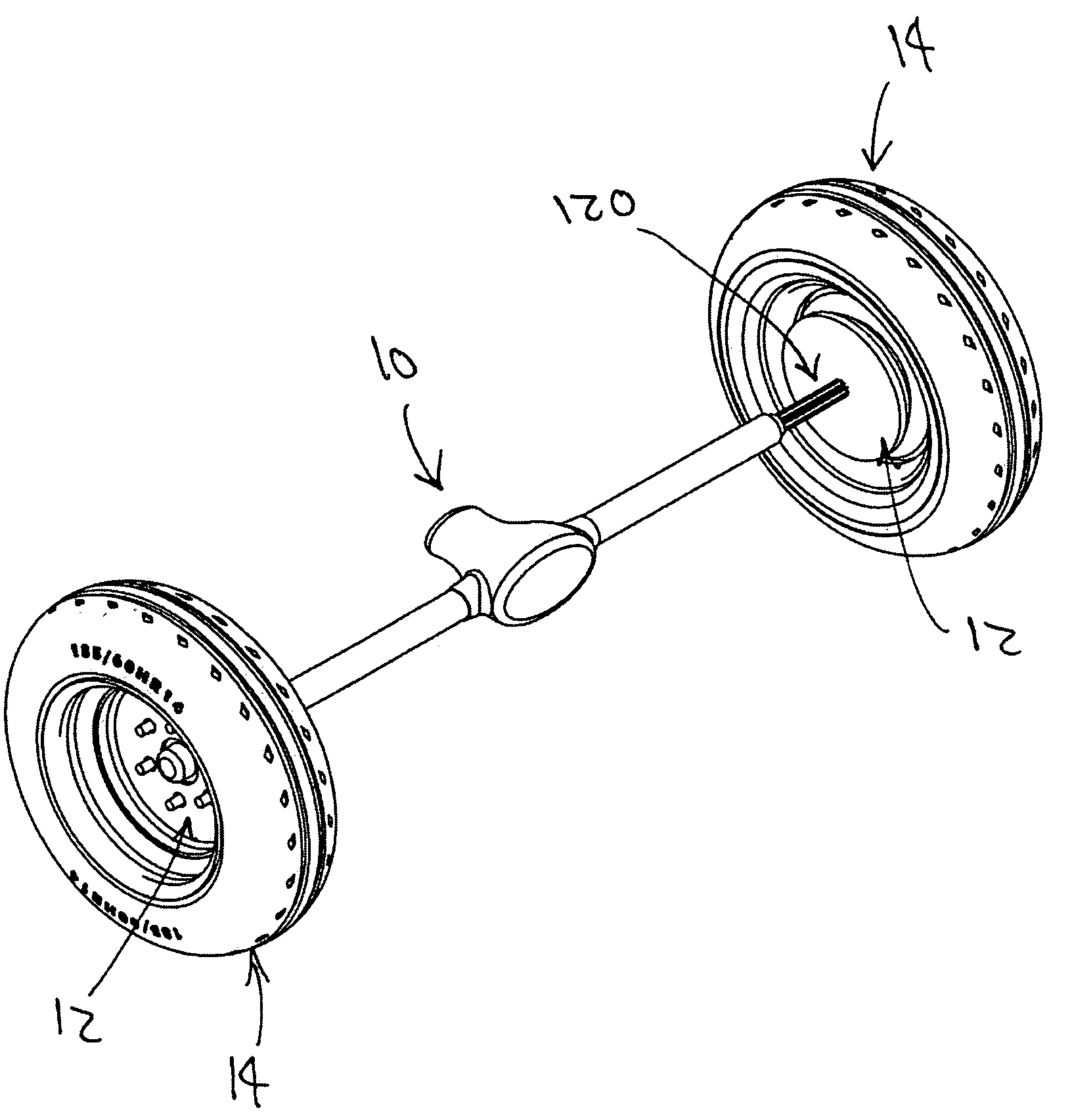
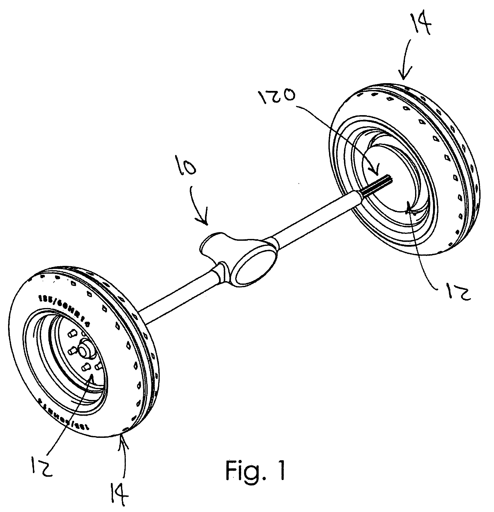
[0030]A vehicle axle will now be described in detail with reference to FIG. 1 through FIG. 8 of the accompanying drawings. More particularly, the vehicle axle 100 includes a main axle 110 and a shaft 120.

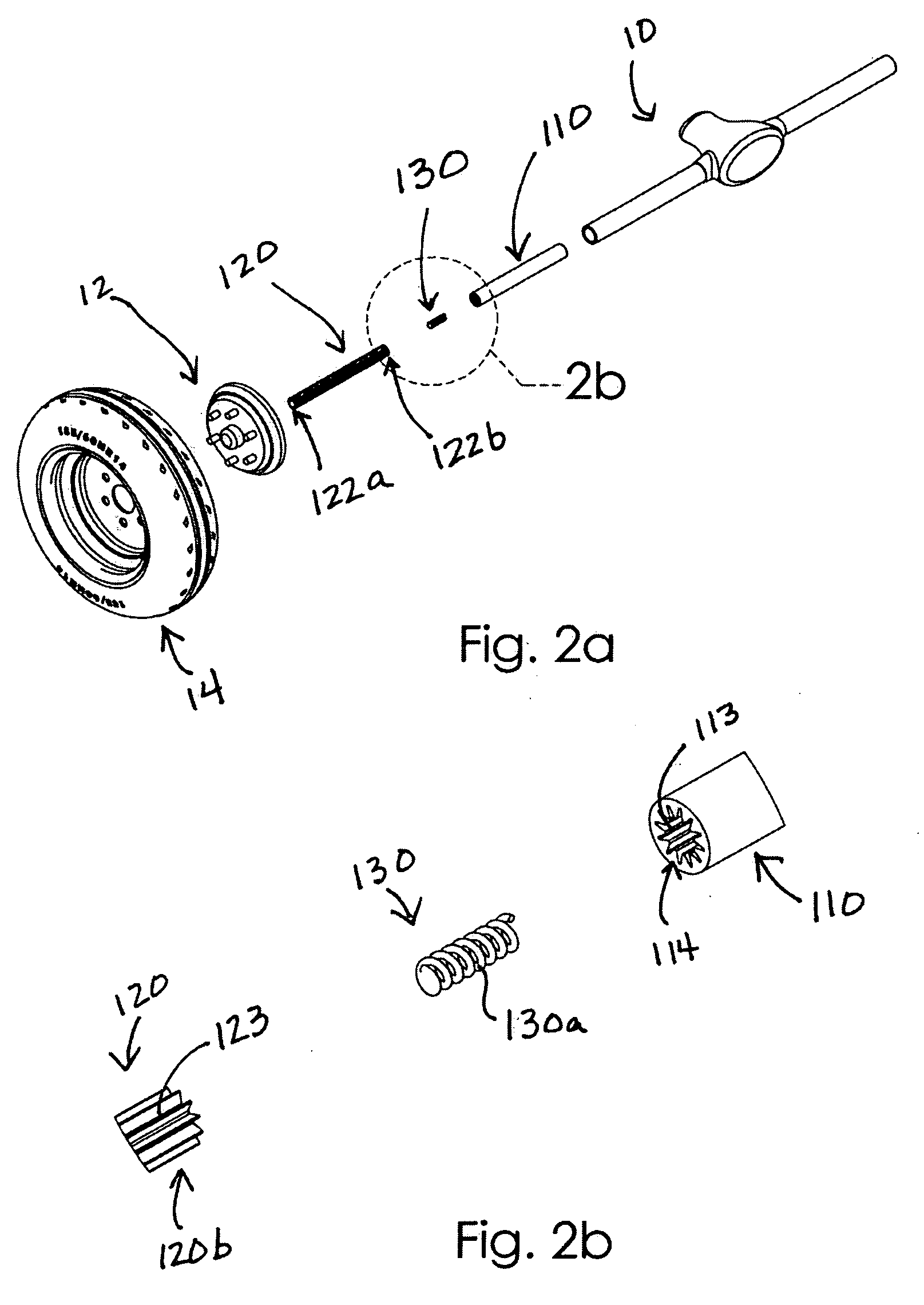
[0031]As shown in FIGS. 2a and 2b, the main axle 110 may be coupled to a vehicle's differential 10 or otherwise coupled to an automobile. The shaft 120 is elongate, has opposed ends 122a, 122b, and is coaxial with the main axle 110. Shaft end 122a is configured to be coupled to a vehicle hub 12, which is in turn coupled to a tire 14 as shown in FIG. 1. The shaft 120 is coupled to the main axle 110 and is movable relative to the main axle 110 along the shared axis. In other words, the shaft 120 can move along the shared axis so that the shaft end 122a moves toward and away from the main axle 110.

[0032]The shaft 120 may include a plurality of splines 123, and the main axle 110 may include a plurality of splines 113 that are complementary to the shaft splines 123. Interaction between t...


PUM


Abstract

A vehicle axle includes a main axle having an end defining a splined cavity. The vehicle axle further includes a splined shaft coaxial with the main axle, the splined shaft having a configuration that is complementary to a configuration of the splined cavity. The shaft and the main axle are coupled together by the shaft splines and the cavity splines, the shaft being movable relative to the main axle along the axis. The vehicle axle includes a force-absorbing member located inside the splined cavity and being in communication with the main axle and the splined shaft so as to absorb force when the splined shaft moves toward the main axle past an equilibrium point.

Description

BACKGROUND OF THE INVENTION[0001]The present invention relates generally to automobile axles and, more particularly, to an automobile axle having a lateral shock absorber. Side impact forces and horizontal stresses related to cornering are decreased by the present invention.[0002]When a force is applied to a car in a horizontal direction, such as a wind load, a side impact, or the centripetal force around a corner, the force will be felt first by the tires and they will bend slightly. This may lead to undesirable accelerated tire wear. If the force is great enough, the tires may begin to slip on the pavement, resulting in a loss of control.[0003]Various devices have been proposed in the art for reducing side impact stresses upon a vehicle. Although assumably effective for their intended purposes, the existing devices do not adequately absorb horizontal stresses such that tire wear is reduced and the damage from side impact collisions is significantly reduced.[0004]Therefore, it woul...

Claims


Application Information

Patent Timeline
Patent Type & Authority Applications(United States)
IPC IPC(8): B60B35/00
CPCB60B35/12B60B35/14B60Y2200/11B60B2900/131B60B2310/307
Inventor BROOKS, MARK
Owner BROOKS MARK
Learn More