
Haptic user interface

a user interface and haptic technology, applied in the field of haptic signals, can solve the problems of not providing information on the position of the closest active area, user does not know the correct position of his fingers, and cannot know the position of the correct active area, so as to reduce the power consumption of generating, speed up the data input significantly, and improve the user experience

Inactive Publication Date: 2009-12-10
NOKIA CORP
View PDF28 Cites 67 Cited by
  • Summary
  • Abstract
  • Description
  • Claims
  • Application Information

AI Technical Summary

Benefits of technology

[0019]An advantage of the present invention is that the user is able to perceive information indicating a direction on the surface of the user interface. This enables the user to move the input means, for example a finger, in the indicated direction, if desired.
[0052]If the symbol moves across the user interface surface, the user may not have to move the input means in order to be able to perceive the haptic signal. To further simplify the understanding of the haptic signal, the symbol can move in the direction to be indicated. An arrow pointing from a starting position to a target position can move towards it and disappear when it eventually arrives at said target position. It can then reappear at the starting position and repeat said movement.

Problems solved by technology

However, the user does not know where the correct position for his fingers is to be found until he has actually reached it.
Of course, this does also not provide information to on the position of the closest active area.

Method used


Image

  • Haptic user interface
  • Haptic user interface
  • Haptic user interface

Examples


Embodiment Construction

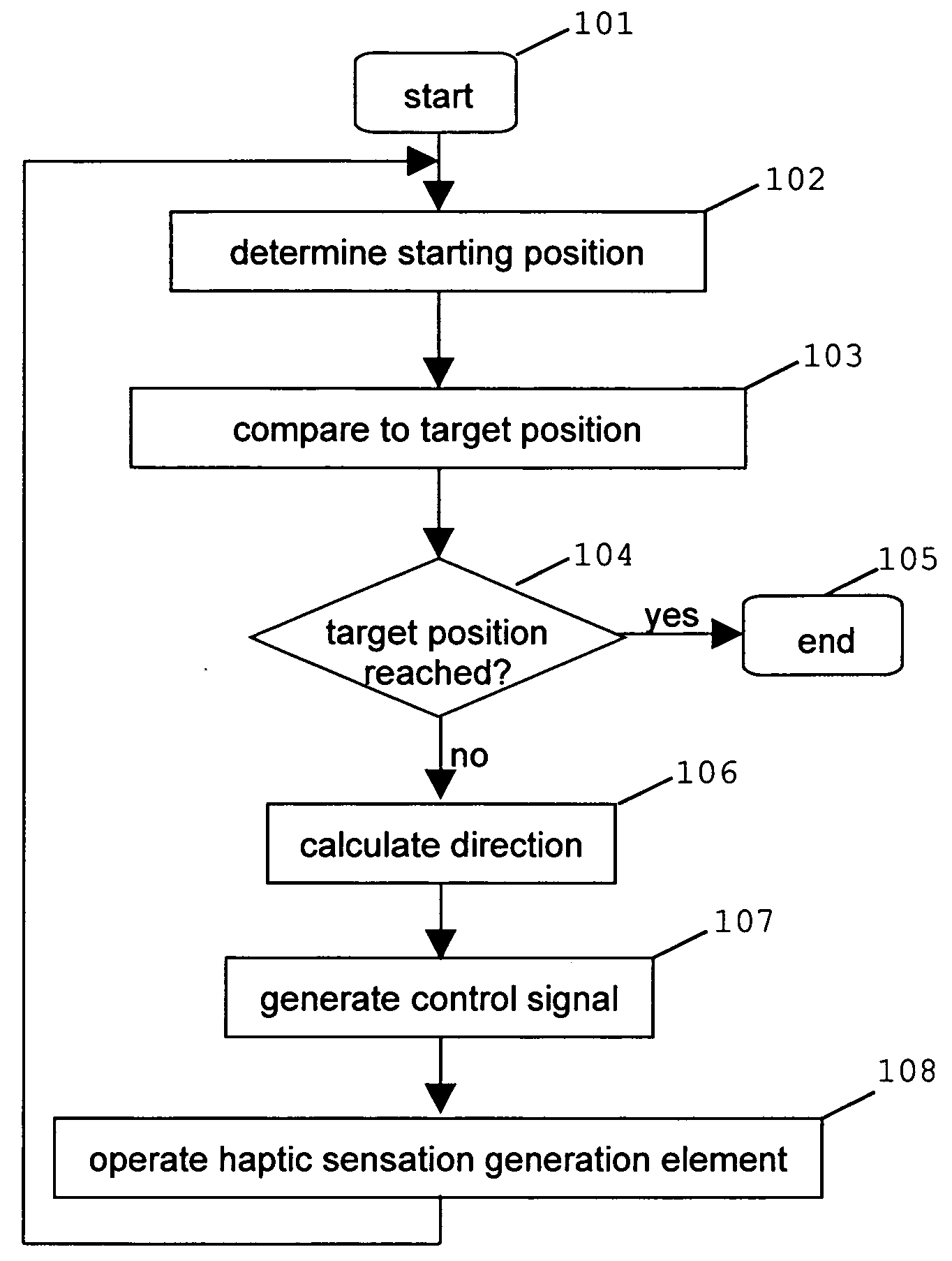
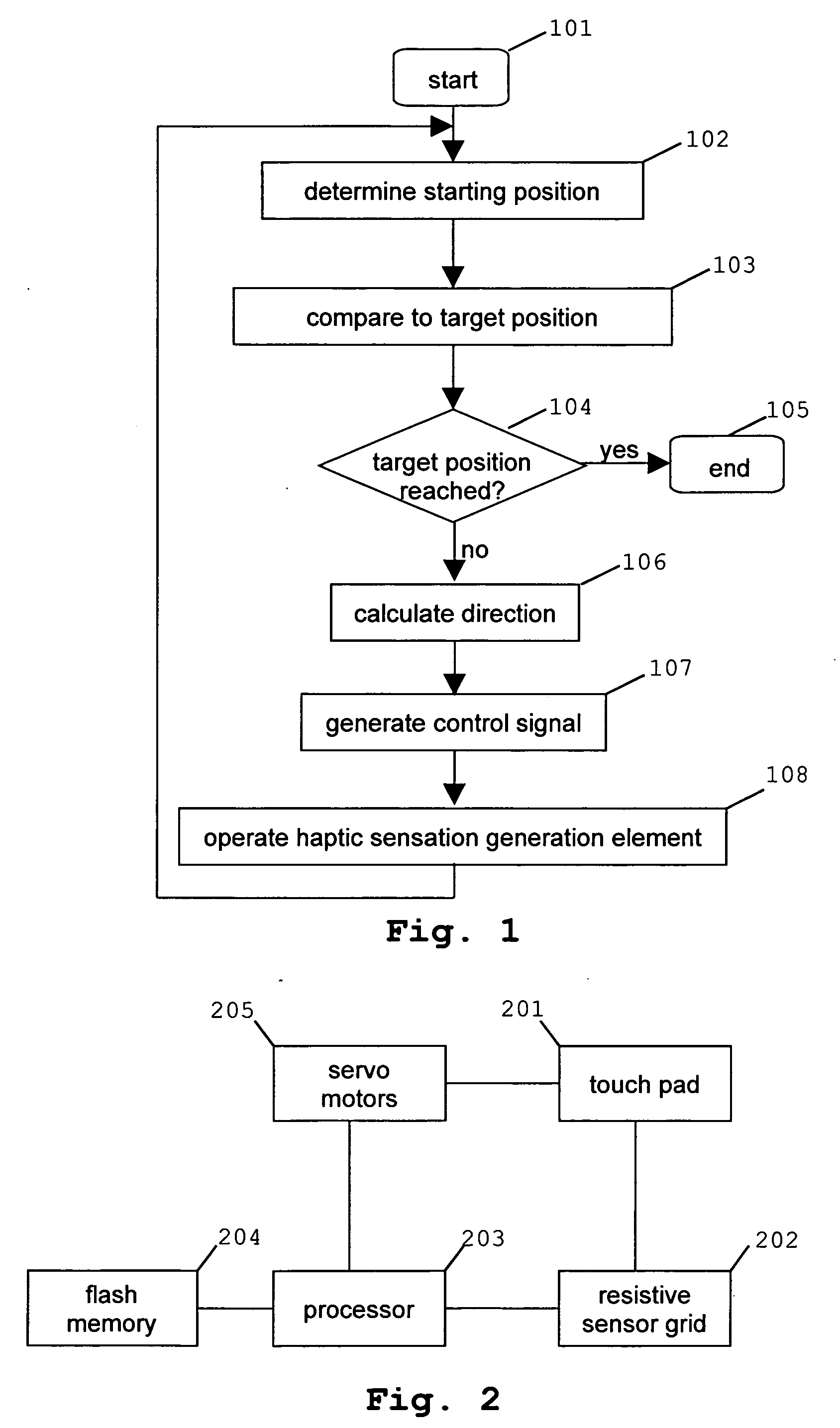
[0061]FIG. 1 is a flow chart exemplarily illustrating the control flow of an exemplary embodiment of the present invention.

[0062]Step 101 is the starting point. Step 102 comprises determining the starting position, i.e. the surface position where the input means (device), such as a stylus or a user's finger, currently contact the user interface surface.

[0063]The information on the starting position obtained in step 102 is then compared to the target position in step 103. The target position has, for example, been previously generated by a computer and is the position the user is most likely to aim for in the present situation of use. In the case, determining the target position is based on a priori knowledge.

[0064]Step 104 consists of checking whether the input means have reached the target position, i.e. whether the starting position and the target position are identical. If they are identical, the process terminates in step 105. If they are not identical, the direction from the st...


PUM


Abstract

This invention relates to a method, apparatuses and a computer-readable medium having a computer program stored thereon, the method, apparatuses and computer program using a haptic signal perceptible by a user contacting a user interface surface with an input means (device) to indicate a predetermined direction on the user interface surface.

Description

TECHNICAL FIELD[0001]This invention relates to the generation of haptic signals for indicating the direction of a user interface surface position to a user.BACKGROUND OF THE INVENTION[0002]User interfaces are used in a variety of applications. They serve for providing user instructions to, among many others, computers, mobile phones, television set-top boxes or personal digital assistants. In industrial applications, for instance, user interfaces are used for controlling a manufacturing process.[0003]Many user interface technologies rely on input means contacting the user interface surface. Within this category fall keyboards having buttons to be pressed by a user in order to make, for instance, a computer processor perform a certain action. In this case, the signal generated is an electrical signal. Usually, different buttons are associated with different actions being performed by the processor.[0004]Other user interfaces are, for example, touch pads or touch screens. These device...

Claims


Application Information

Patent Timeline
Patent Type & Authority Applications(United States)
IPC IPC(8): G09G5/00G06F3/041
CPCA63F13/10A63F2300/1037A63F2300/1075G06F3/016G09B21/003G06F3/04842G06F3/04883G06F2203/014G06F3/041G06F2203/04809G06F3/04886A63F13/285G06F3/02G06F3/03545A63F13/40A63F13/2145
Inventor KOIVUNEN, RAMI ARTO
Owner NOKIA CORP
Learn More