Patient positioning imaging device and method

a positioning device and positioning technology, applied in the field of patient positioning imaging apparatus and method, can solve the problems of unpractical full rotation of a heavy gantry structure for obtaining images, the beam could damage healthy cells within the patient's body, and the x-ray tube inside the nozzle is too small, so as to achieve smooth folding of the positioning device

Inactive Publication Date: 2009-12-10
ION BEAM APPL
View PDF29 Cites 124 Cited by
  • Summary
  • Abstract
  • Description
  • Claims
  • Application Information

AI Technical Summary

Benefits of technology

[0019]In an advantageous embodiment the pivoting arm and the pivoting structure have a different length. This allows smoothly folding the positioning device.

Problems solved by technology

Otherwise, the beam could damage healthy cells within the patient's body.
Because of the nozzle frame and the aperture support, the field of view using the X-ray tube inside the nozzle would be too small,full rotation of a heavy gantry structure for obtaining images is felt as unpractical.
An alternative possible solution would be to position a CBCT system in the treatment room, which clearly would use treatment room space and thus be an inconvenience for the therapists.

Method used


Image

  • Patient positioning imaging device and method
  • Patient positioning imaging device and method
  • Patient positioning imaging device and method

Examples


Embodiment Construction

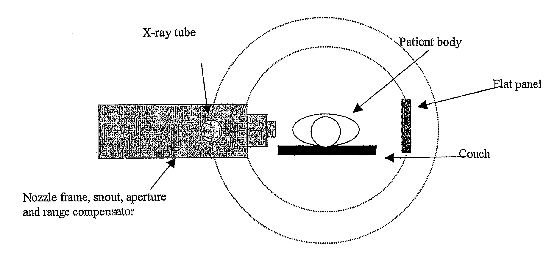
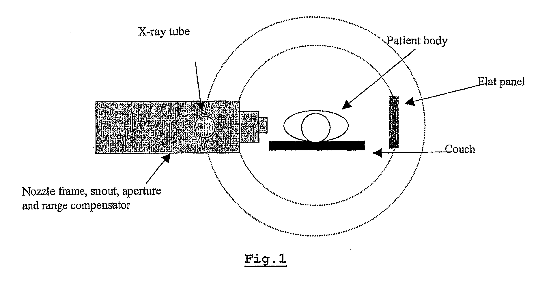
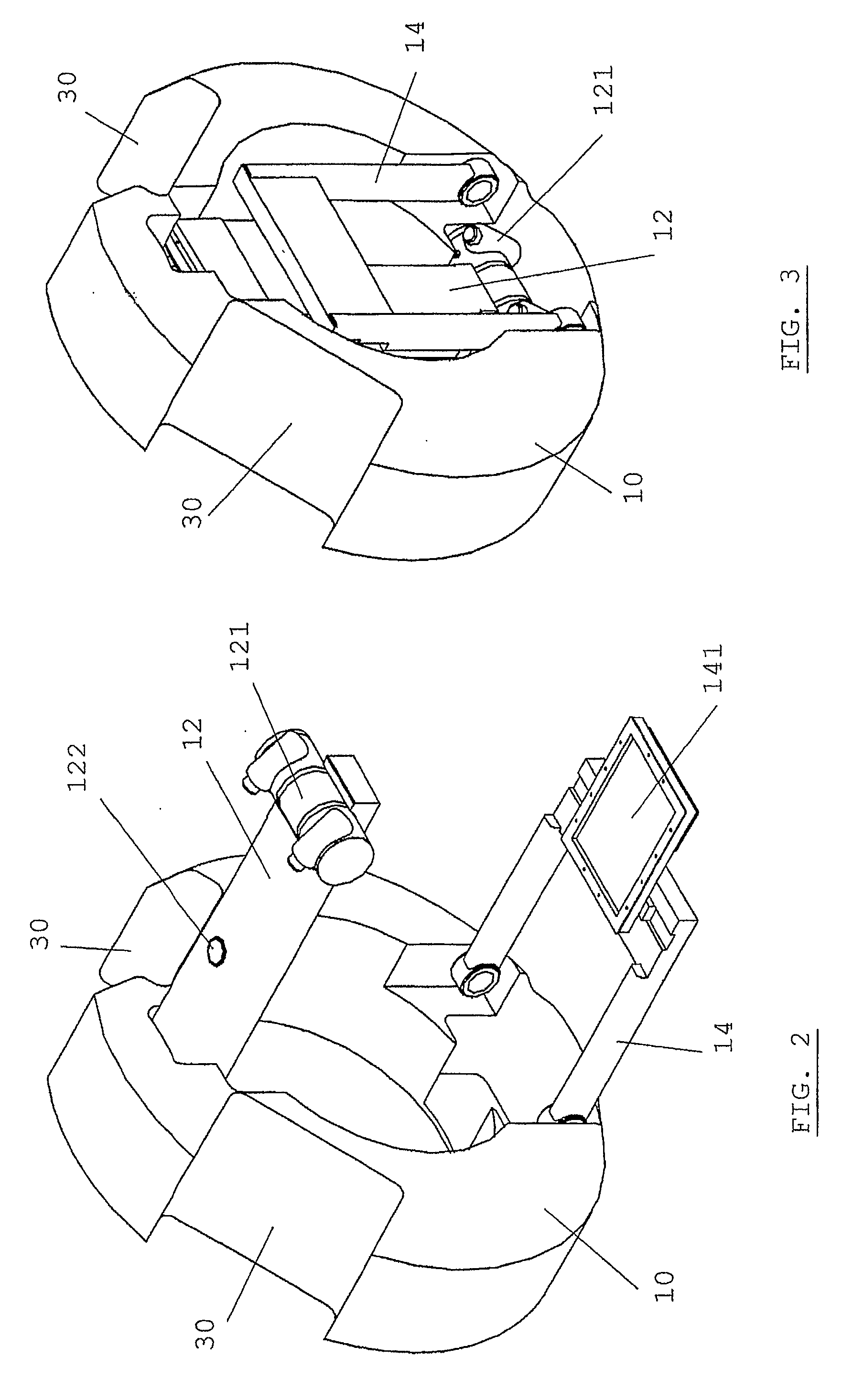
[0043]The present invention discloses a patient positioning imaging device and method for positioning a patient in a hadron therapy device. To overcome the above-mentioned constraints, the solution according to the present invention consists in providing a patient positioning imaging system comprising a small and light rotatable structure inside the gantry of the beam therapy device. This offers several advantages:[0044]it allows to have enough space to install the X-ray tube and the flat panel at the same distance as in conventional radiotherapy (RT).[0045]it allows to have the full field of view as in conventional RT,[0046]it allows to have a system fully independent from the orthogonal flat panels. There is no need to rotate anything when taking orthogonal shots.[0047]no treatment room space is used so that it remains fully available for the therapists.[0048]the room for the gantry rolling floor remains available and there is no need to move the floor during the rotation of the C...


PUM


Abstract

The present invention is related to a patient positioning imaging device for positioning a patient in a hadron therapy device provided with a rotatable gantry (20). The patient positioning imaging device comprises a rotatable structure (10) provided with an extensible arm or foldable pivoting arm (12) arranged for connecting an imaging beam source (121) and an extensible structure or foldable pivoting structure (14) arranged for carrying an imaging beam receiver (141). The rotatable structure (10) is arranged for taking CBCT shots of the patient while the patient is located in an offset position with respect to an isocentre of the hadron therapy device, said offset position being in the direction of a rotational axis of the rotatable gantry (20). The rotatable structure (10) is arranged for being rotated while the rotatable gantry (20) remains fixed, and while the extensible or pivoting arm (12) and the extensible or pivoting structure (14) are in extended or unfolded position.

Description

FIELD OF THE INVENTION[0001]The present invention is related to a patient positioning imaging apparatus and method for positioning a patient in a hadron therapy device.STATE OF THE ART[0002]When a malignant tumour has been discovered in a patient's body, the tumour first needs to be visualised for further examination. This can for example be performed with a (third generation) 3D computed tomography (CT) scanning system. With the information collected in this way a clinical treatment plan can be generated. Then the actual treatment with a therapeutic apparatus can start.[0003]In a known hadron therapy apparatus, like e.g. used in proton therapy, the therapeutic radiation beam, accelerated by an accelerator such as a cyclotron, is guided to the therapy room where the patient is fixed to a therapy table such as a therapy couch. Prior to irradiation, the therapy table must be positioned accurately by means of a positioning system, such that the affected part of the patient's body is in...

Claims


Application Information

Patent Timeline
Patent Type & Authority Applications(United States)
IPC IPC(8): A61N5/10H05G1/02
CPCA61N5/1049A61N5/1069A61N2005/1087A61N2005/1061A61N5/1081A61N5/10
Inventor AMELIA, JEAN-CLAUDEGENIN, FREDERIC
Owner ION BEAM APPL
Why Eureka
Try Eureka