
Hip Support Member

a hip support and support member technology, applied in the field of hip support members, can solve the problems of wearer discomfort, high laborious process of forming a support member, and inability to meet the needs of wearer, so as to reduce the discomfort of wearer, reduce the cost of the hip support member, and improve the rigidity

Active Publication Date: 2009-12-10
HONDA MOTOR CO LTD
View PDF2 Cites 19 Cited by
  • Summary
  • Abstract
  • Description
  • Claims
  • Application Information

AI Technical Summary

Benefits of technology

[0006]It is highly important for the (exoskeletal) support member of a walking assistance device to be able to fit the body contour of the wearer when worn on the body (hip portion) of the wearer. As a method for achieving a desired fit, it has been practiced in conventional medical support members to use a thermoplastic plastic material and shape it by directly applying it to the body of the user. Thereby, the support member is enabled to closely fit each particular wearer, and the comfort of the wearer can be improved.
[0008]In view of such problems of the prior art, a primary object of the present invention is to provide a hip support member that reduces the discomfort to the wearer during use while accommodating the differences in the build of different wearers,Means to Achieve the Task
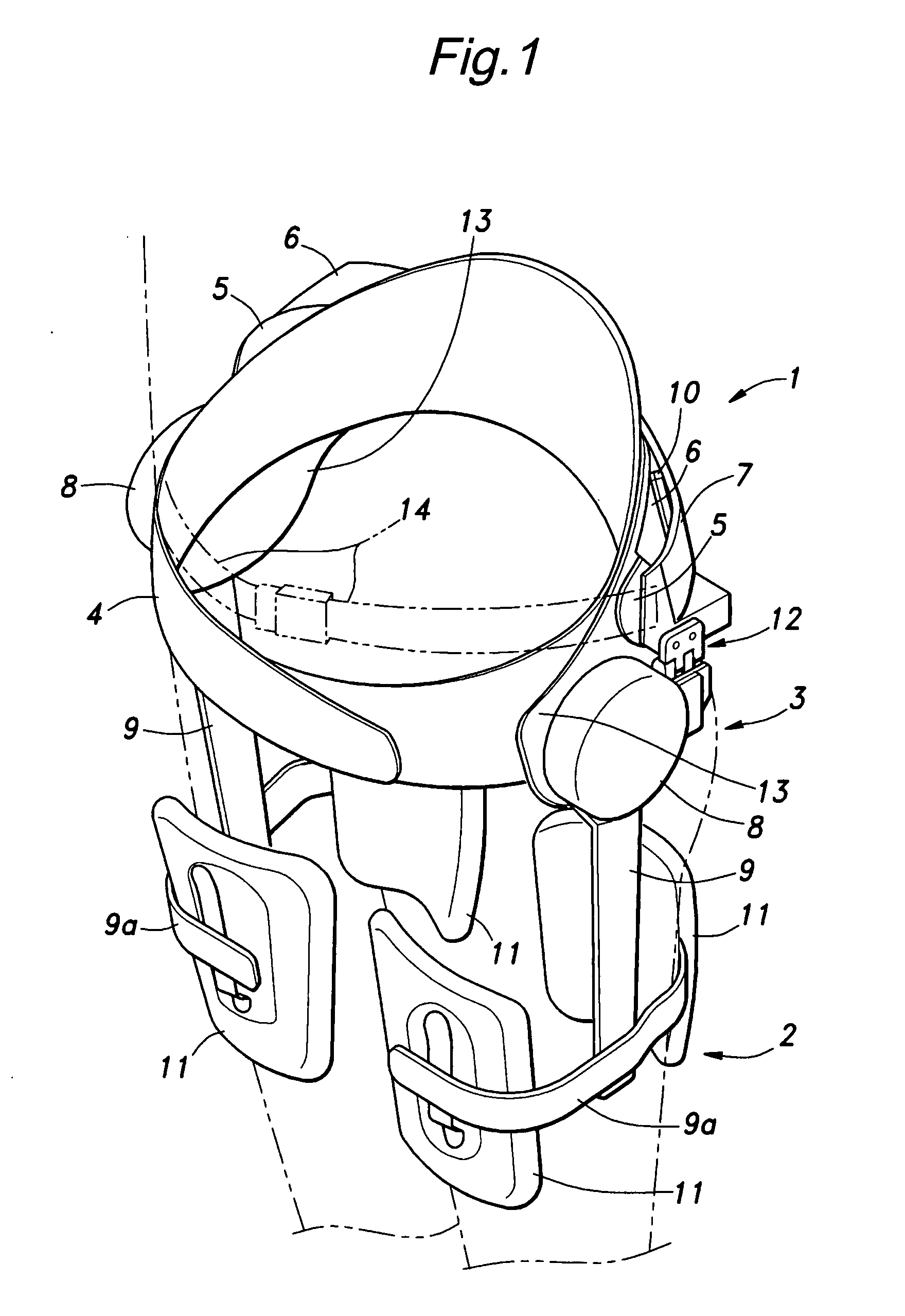
[0009]To achieve such an object, the present invention provides a hip support member for enabling a wearer to wear a frame (7) made of a rigid member for carrying a heavy object, comprising: a hip protective belt (4) having a flexibility that allows the hip protective belt to conform to a body contour of the wearer and wrapped around a hip of the wearer; and an intermediate member (5, 6) interposed between the hip protective belt and frame and having a rigidity intermediate between those of the hip protective belt and frame so as to absorb a difference in deformation between the hip protective belt and frame.
[0010]Thus, when using a frame made of a rigid member for carrying a heavy object, by providing an intermediate member between a hip protective belt wrapped around the hip of the wearer and frame, and selecting the rigidity of the intermediate member so as to be intermediate between those of the hip protective belt and frame, the feel of the rigidity of the frame is mitigated by the intermediate member before it is transmitted to the wearer via the hip protective belt, and the wearer would not feel constrained by the frame even when the wearer changes his posture during use. Also, because the frame would not deform while the hip protective belt can readily deform itself so as to conform to the body contour of the wearer, even when a difference (gap) is created between the hip protective belt and frame depending on the build of the particular wearer, this difference can be absorbed by the elastic deformation of the intermediate member, and the frame can accommodate a certain range of the builds of potential wearers. Therefore, when the frame is prepared in three different sizes S, M and L, it can essentially fit most of the population. This helps to reduce the cost of the hip support member by allowing the frame to be prepared as a ready made component as opposed to a custom made frame.
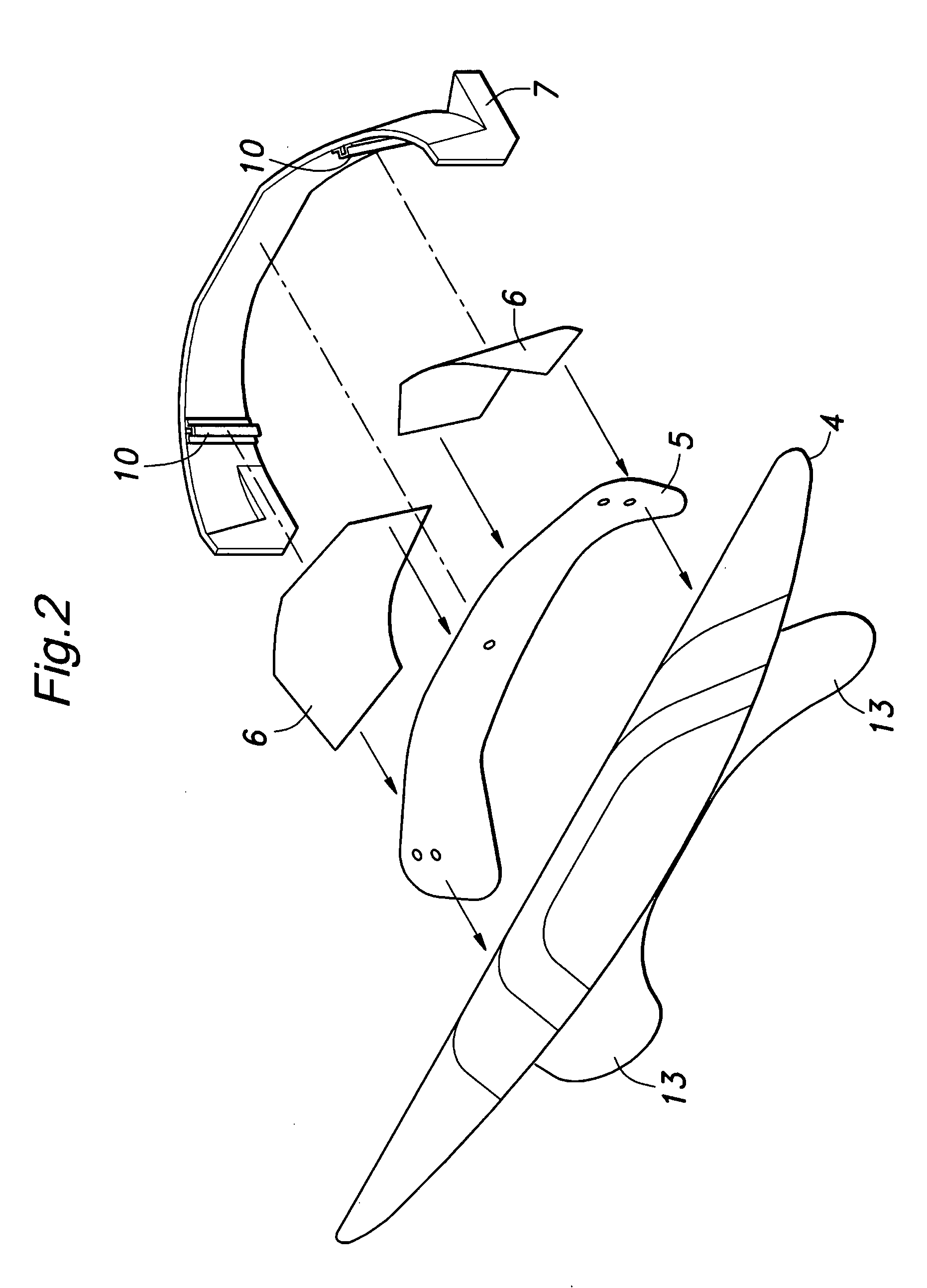
[0011]In particular, it is preferable that the intermediate member comprises a flexible body-side plate (5) arranged on an outer side of the body of the wearer and pliant enough to conform to an outer contour of the hip of the wearer and an outer plate (6) arranged on an outer side of the body-side plate and locally engages the body-side plate at a higher rigidity than the body-side plate. These plates may comprise resiliently deformable plate members. Thus, the intermediate member makes the transition in rigidity from the frame to the hip protective belt into a gradual one and the pressure from the frame is transmitted to the body-side plate via the outer plate so that the pressure from the rigid frame is prevented from being directly applied to the body of the wearer.
[0012]In view of the cross sectional shape and anatomy of the hip of a wearer, the outer plate (6) may comprise two sections that are located between the body-side plate (5) and frame on either side of a spine of the wearer, and each section comprises a middle part pivotally supported by the frame and two ends that curve away from the frame and engage the body-side plate. For similar reasons, the hip protective belt may be provided with a plurality of layers, the layers being largest in number at a part thereof corresponding to the back of the wearer and being progressively reduced in number toward each side end. Thereby, the central part of the hip protective belt is allowed to oppose the recess in the center of the back, and this enhances the stability of the hip protective belt when worn by a wearer.

Problems solved by technology

However, it is a highly laborious process to shape a support member for each individual wearer, and the cost inevitably rises similarly as the case of a custom made production.
Also, when an athletic hip supporter is used, since it is typically provided with a lozenge shaped back portion that broadly covers the hip area, and a plurality of ribs provided in the back portion reduce the flexibility thereof, the wearer tends to experience discomfort owing to the excessive rigidity of the back portion depending on the posture of the wearer.

Method used


Image

  • Hip Support Member
  • Hip Support Member
  • Hip Support Member

Examples


Embodiment Construction

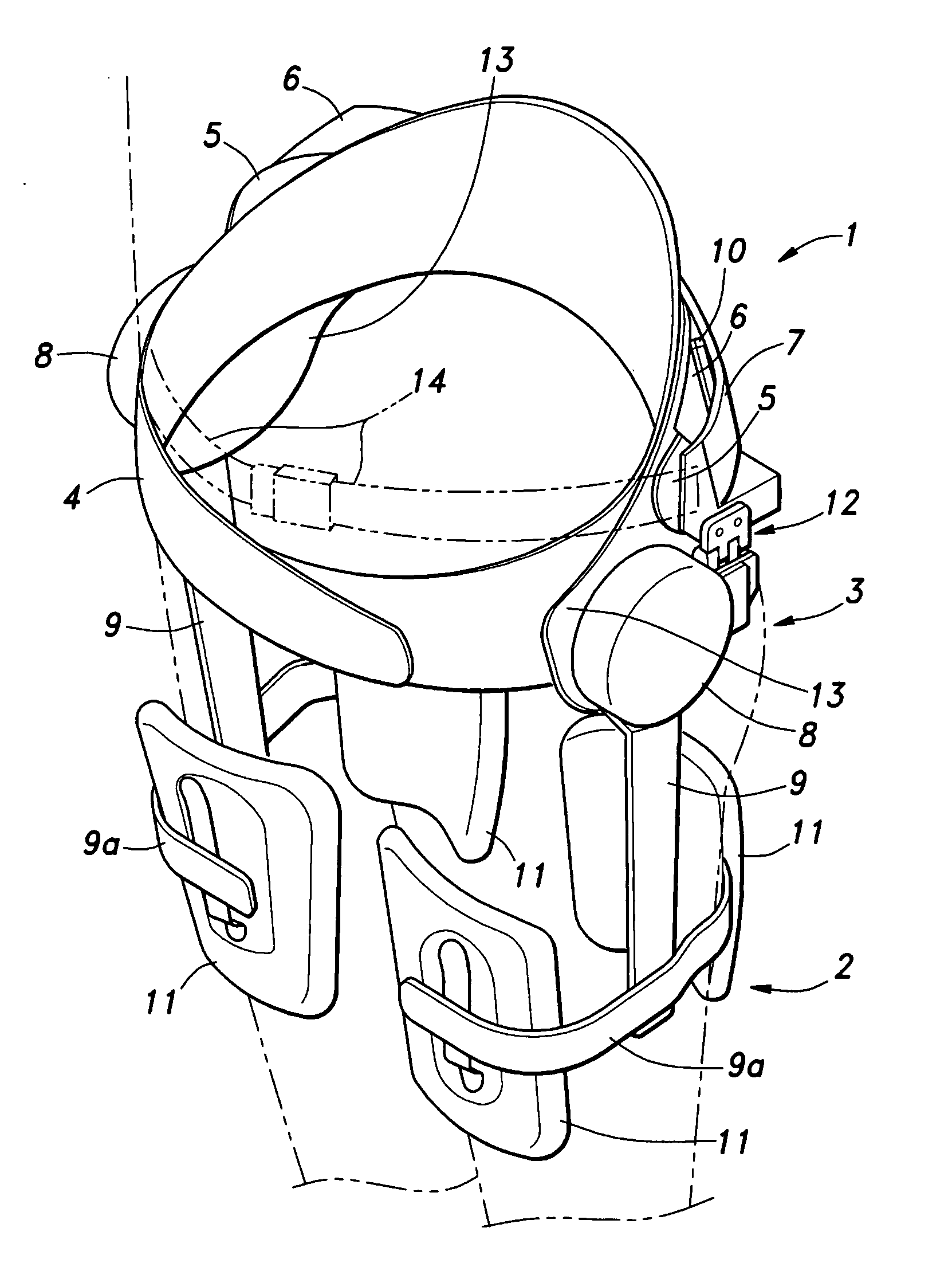
[0020]FIG. 1 is a simplified structural view of a walking assistance device embodying the present invention as worn on the body of a wearer (indicated by the double-dot chain-dot line). This walking assistance device comprises a hip support member 1, a pair of femoral support members 2 and a pair of drive units 3 for producing an assist power. By wearing the hip support member 1 on the hip of the wearer and each femoral support member 2 on the corresponding femoral region T of the wearer, the torque produced by the drive unit 3, which is supported by the hip support member 1 and connecting the two support members 1 and 2 to each other, is transmitted to the femoral region T of the wearer so that an assist force that would compensate for the reduced muscle power of the wearer is given to the wearer.

[0021]As also shown in FIG. 2, the hip support member 1 comprises a hip protective belt 4 made of fabric, for instance, and wrapped around the hip of the wearer, a flexible plate (body-sid...


PUM


Abstract

When securing a frame (7) made of a rigid member for carrying a heavy object such as a drive unit (3) for a walking assistance device on the hip of a wearer, a hip protective belt (4) made of fabric is wrapped around the hip of the wearer, and the frame (7) is secured thereon via a flexible plate (5) and a pressure plate (6) located on an outer side of the flexible plate (5) and having a higher rigidity than the flexible plate (5). The intermediate members allow the wearer to feel the rigidity of the frame in a mitigated manner, and the wearer would not experience any discomfort from the pressure of the frame even when the posture of the wearer is changed. The hip protective belt can readily conform to the body contour of the wearer, but the frame would not deform. Because the intermediate members absorb the difference in the builds of different wearers, the frame may come in a small number of different sizes to fit almost any wearer. Thereby, the hip support member can be mass produced at low cost.

Description

TECHNICAL FIELD[0001]The present application claims priority from Japanese application No. 2005-143424 filed May 17, 2005, and the contents of this Japanese patent application are incorporated in the present application by reference.[0002]The present invention relates to a hip support member for enabling a wearer to carry on the hip of the wearer a heavy object such as a walking assistance device for providing an assistance to a person who has a difficulty in walking by himself owing to the lack of muscular force.BACKGROUND OF THE INVENTION[0003]Various walking assistance devices have been proposed for the purpose of providing an assistance to a person who has a difficulty in walking by himself owing to the lack of muscular force caused by external injuries, diseases and aging, and such a device typically includes a power actuator fitted on the wearer near his hip joint or knee joint to assist the movement of his lower limbs. Conventionally, in such a walking assistance device, it w...

Claims


Application Information

Patent Timeline
IPC IPC(8): A61F5/00
CPCA61F5/0193A61H2003/007A61H3/00A61H1/0244
Inventor HIRATA, TAKASHISHIMADA, KEIFUJII, TAKAKO
Owner HONDA MOTOR CO LTD
Learn More