Bone Fixation Assemblies and Methods of Use

a technology of bone fixation and assembly, which is applied in the field of bone fixation assembly, can solve the problems of weak implants, difficult for orthopedic and difficult for operating surgeons to fix distal femur fractures

Active Publication Date: 2009-12-10
TEENY STEVEN M
View PDF12 Cites 18 Cited by
  • Summary
  • Abstract
  • Description
  • Claims
  • Application Information

AI Technical Summary

Benefits of technology

[0009]The teachings herein are directed to assemblies for fixing a fractured bone that include an intramedullary nail having proximal and distal ends and is configured to be implanted within an intramedullary canal of the fractured bone, a blade configured to be implanted into a fractured fragment, and having distal and proximal ends, a horizontal plane adjoined by one or more ou

Problems solved by technology

Fractures located near the proximal or distal ends of a patient's bone are often problematic for the operating surgeon to fix.
Distal femur fractures are often difficult for an orthopedic surgeon to fix because of their proximity to the knee and their frequent association with patients having a total joint replacement covering the end of the bone and/or those suffering from osteoporosis.
More specifically, affixing pins, screws, plates, and/or an intramedullary nail in a brittle bone having low mineral density, can often lead to undesirable results.
One of the potential disadvantages of the Schon et al. design is that the final configuration is substantially an “L-shape” implant, where the intramedullary nail is secured through a passageway adjacent to the proximal end of the blade (See Schon et al. FIG. 1).
One of the disadvantages to the “L-shape” configuration is that it may result in a weaker impl

Method used


Image

  • Bone Fixation Assemblies and Methods of Use
  • Bone Fixation Assemblies and Methods of Use
  • Bone Fixation Assemblies and Methods of Use

Examples


Embodiment Construction

[0023]Embodiments of the present invention are described below with reference to the above described Figures. It is, however, expressly noted that the present invention is not limited to the embodiments depicted in the Figures, but rather the intention is that modifications that are apparent to the person skilled in the art and equivalents thereof are also included.

Intramedullary (IM) Nail / Rod

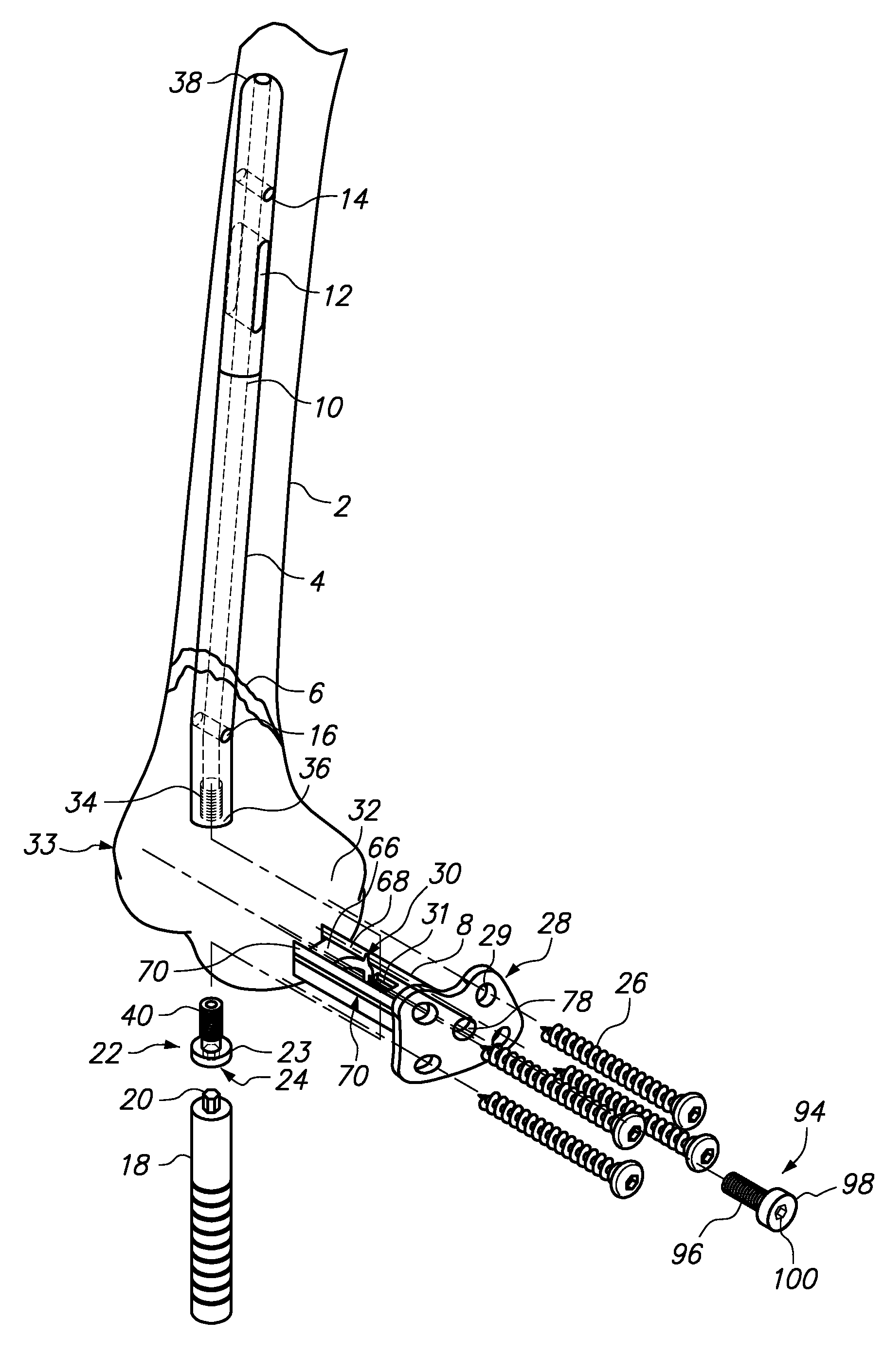
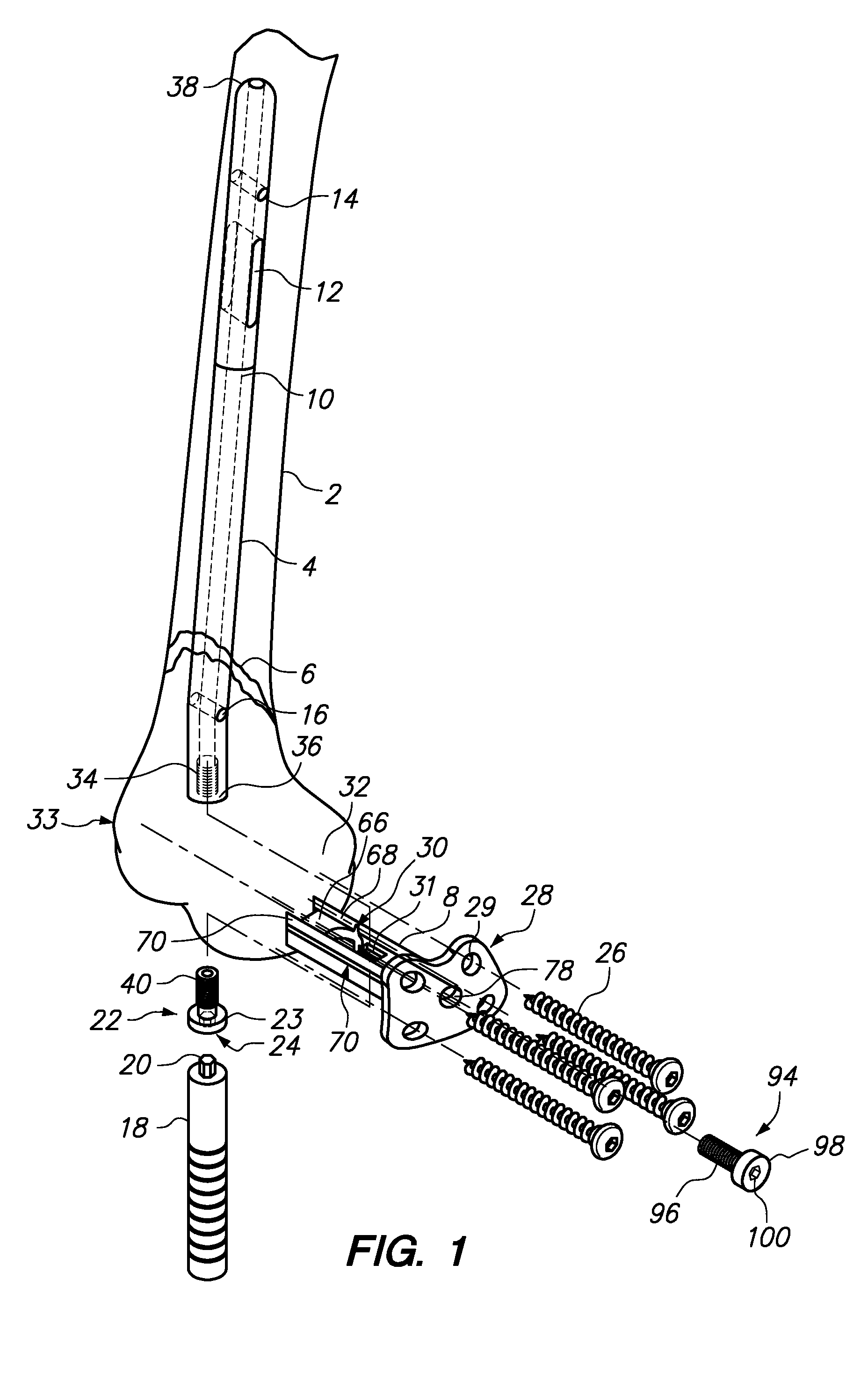
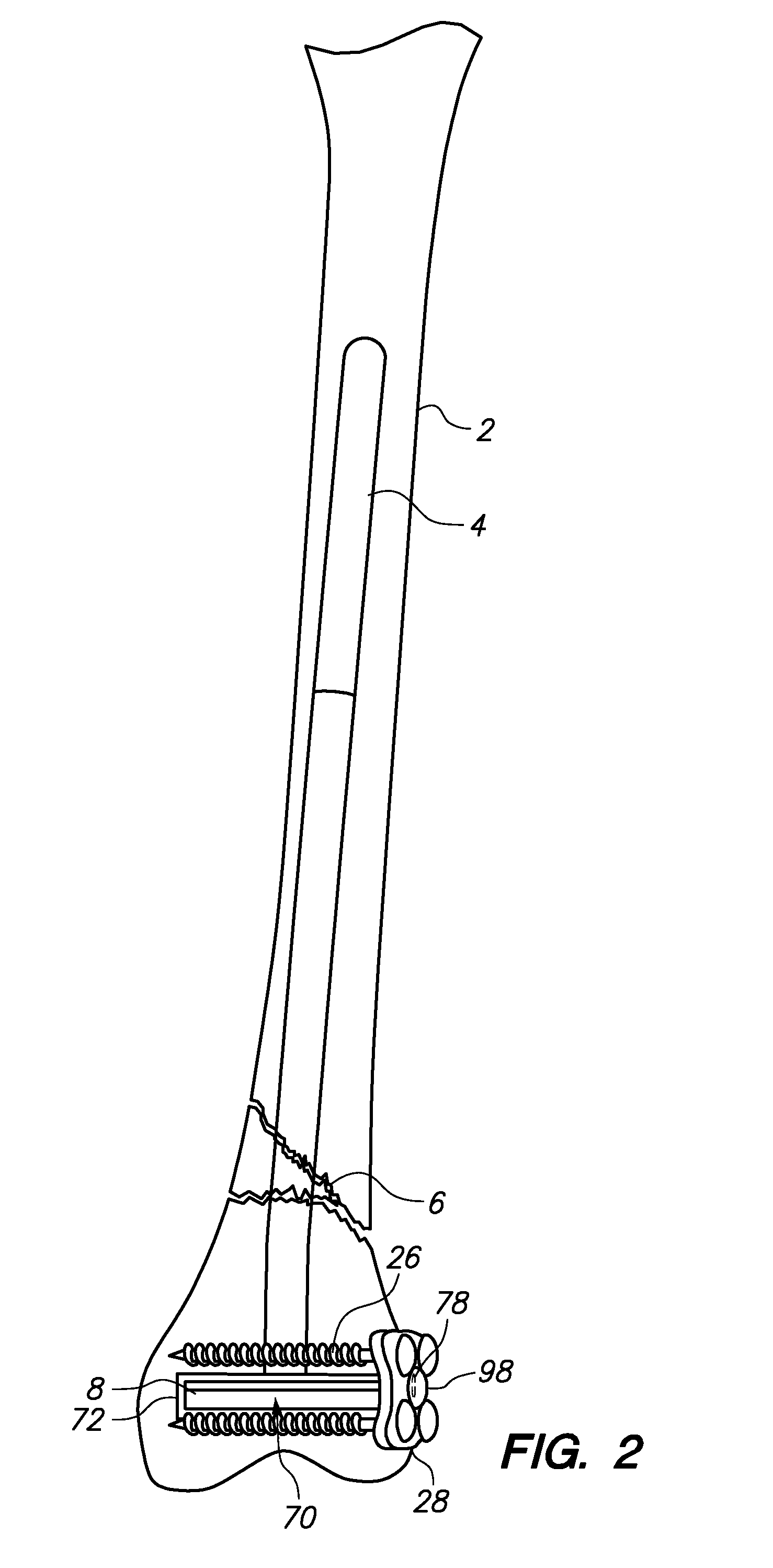
[0024]FIG. 1 depicts an exploded view of a preferred IM nail 4 and blade 8 assembly being positioned in a patient's left femur 2 to treat a fracture 6. As used herein, the terms “intramedullary nail,”“IM nail,”“intramedullary rod,” and “IM rod” can be used interchangeably. The IM nail 4 is preferably configured and selected to be positioned into the patient's medullary cavity of the femur 2 such that it passes through the fractured area 6 of the bone and couples to a blade 8 at its proximal end 36. Accordingly, while the majority portion of the IM nail 4 should extend in a straight line, in pre...


PUM


Abstract

Intramedullary rod and blade assemblies and methods of implanting said assemblies are disclosed herein. The assemblies provided herein are useful in treating distal, proximal fractures, among other conditions, in large bones including, but not limited to: femurs, tibias, and humeri. Preferred assemblies can include an intramedullary rod having a proximal end and coupling means configured to securely attach to a blade, such that no portion of the rod or the coupling means extend into the fractured fragment beyond the blade. Further preferred assemblies include intramedullary rods that connect in the center of the internal blade, or substantially so, such that the rod and blade form a “T-shape,” or substantially so.

Description

FIELD OF THE INVENTION[0001]The embodiments herein relate to bone fixation assemblies and methods of using said assemblies. More particularly, the teachings herein relate to intramedullary rod and blade assemblies and methods of using these assemblies to treat fractures located near the proximal or distal end of a bone (e.g., femur, tibia) and other orthopedic conditions in patients.BACKGROUND[0002]Fractures located near the proximal or distal ends of a patient's bone are often problematic for the operating surgeon to fix.[0003]With respect to the femur, proximal fractures commonly occur in the femoral neck, and in the inter-trochanteric region. Distal femur fractures that occur between the femur and the condyles are termed “supracondylar fractures”. Distal fractures occurring in one or more of the condyles are termed a “condylar” or “intercondylar” fracture.[0004]Distal femur fractures are often difficult for an orthopedic surgeon to fix because of their proximity to the knee and t...

Claims


Application Information

Patent Timeline
IPC IPC(8): A61B17/56
CPCA61B17/725A61B2017/90A61B17/88A61B17/90
Inventor TEENY, STEVEN M.
Owner TEENY STEVEN M
Why Eureka
Try Eureka