Identification marker

a technology of identification markers and identification marks, which is applied in the direction of cables, instruments, mechanical equipment, etc., can solve the problems of difficult to know the type of underground lines to be identified, and achieve the effect of improving visual recognition and convenient installation

Inactive Publication Date: 2009-12-17
BURLANDO ALBERT A
View PDF16 Cites 25 Cited by
  • Summary
  • Abstract
  • Description
  • Claims
  • Application Information

AI Technical Summary

Benefits of technology

[0007]Still another object of the present invention is to provide an improved underground cable identification system of improved visual recognition.
[0008]Yet another object of the present invention is to provide an improved underground cable identification system capable of easy installation.
[0009]These and other objects of the present invention are achieved by a cable marker comprising a flag for connection to a support stake, wherein the flag has a center portion for connection to the support stake and includes a first side portion having a display surface for an identification sign and a second side portion having a display surface for an identification sign. By using a first side portion having a display surface with an identification sign and a second side portion having a display surface with an identification sign, the problem of not knowing the type of underground line being identified by the marker is avoided.

Problems solved by technology

One problem with these cable markers is that it is difficult to know the type of underground line being identified, particularly when the color code of the strands is not known.

Method used


Image

  • Identification marker
  • Identification marker
  • Identification marker

Examples


second embodiment

[0024]FIG. 6 shows the present invention, marker 10a, having parts similar to the parts of marker 10 in FIG. 1, and having the same drawing reference numerals, but with a subscript “a” added thereto. The marker 10a includes a flag 12a and a wire rod stake 50, supporting the flag 12a. The marker 10a is supported by the ground 17a, disposed in a backfilled trench 16a having a cable 18a buried therein. The stake 50 includes a center portion 52, a lower end portion 54, and an upper end portion 56. The upper end portion 56 is formed with a hook portion 58. The center portion 52 includes a loop 60, supporting flag 12a in a vertical direction, as required.

[0025]The flag 12a is identical in construction to the flag 12. It is noted that, as an alternative not shown in FIG. 6, two flags 12a can be stacked, one above the other, upon and supported by wire rod stake 50, where one is disposed at a 90° angle in plan view from the other to provide a four-way view. The stake 50 is preferably made of...

third embodiment

[0026]FIGS. 7 and 8 show the present invention, marker 10b, having parts similar to the parts of marker 10 in FIG. 1, and having the same drawing reference numerals, but with a subscript “b” added thereto. The marker 10b includes a flag 12b and a wire coil stake 80 supporting the flag 12b. The marker 10b is supported by ground 17b disposed in a backfilled trench 16b having a cable 18b buried therein. The stake 80 includes a center portion 82, a lower end portion 84, and an upper end portion 86. The upper end 86 includes a hook portion 88. The center portion 82 and the lower end portion 84 have a plurality of coils 90. The hook portion 88 can be turned by hand in order to screw the marker 10b into the ground 17b when the ground 17b is of a suitable consistency and content.

[0027]The flag 12b is identical in construction to the flag 12. It is noted that, as an alternative not shown in FIGS. 7 and 8, two flags 12b can be stacked, one above the other, upon and supported by wire coil stak...

fourth embodiment

[0028]FIG. 9 shows the present invention, marker 10c, including a first flag 12c, a second flag 100 and a wooden support stake 14c. The flags 12c and 100 are connected to the stake 14c by a nail 15c and are identical in construction to the flag 12 of marker 10 of FIG. 1. The marker 10c provides a four-way view for four-direction identification when flags 12c and 100 are folded as shown for flags 12, 12a, 12b in FIGS. 1, 6, and 7.

[0029]Advantages of the markers 10, 10a, 10b, 10c of the present invention are:

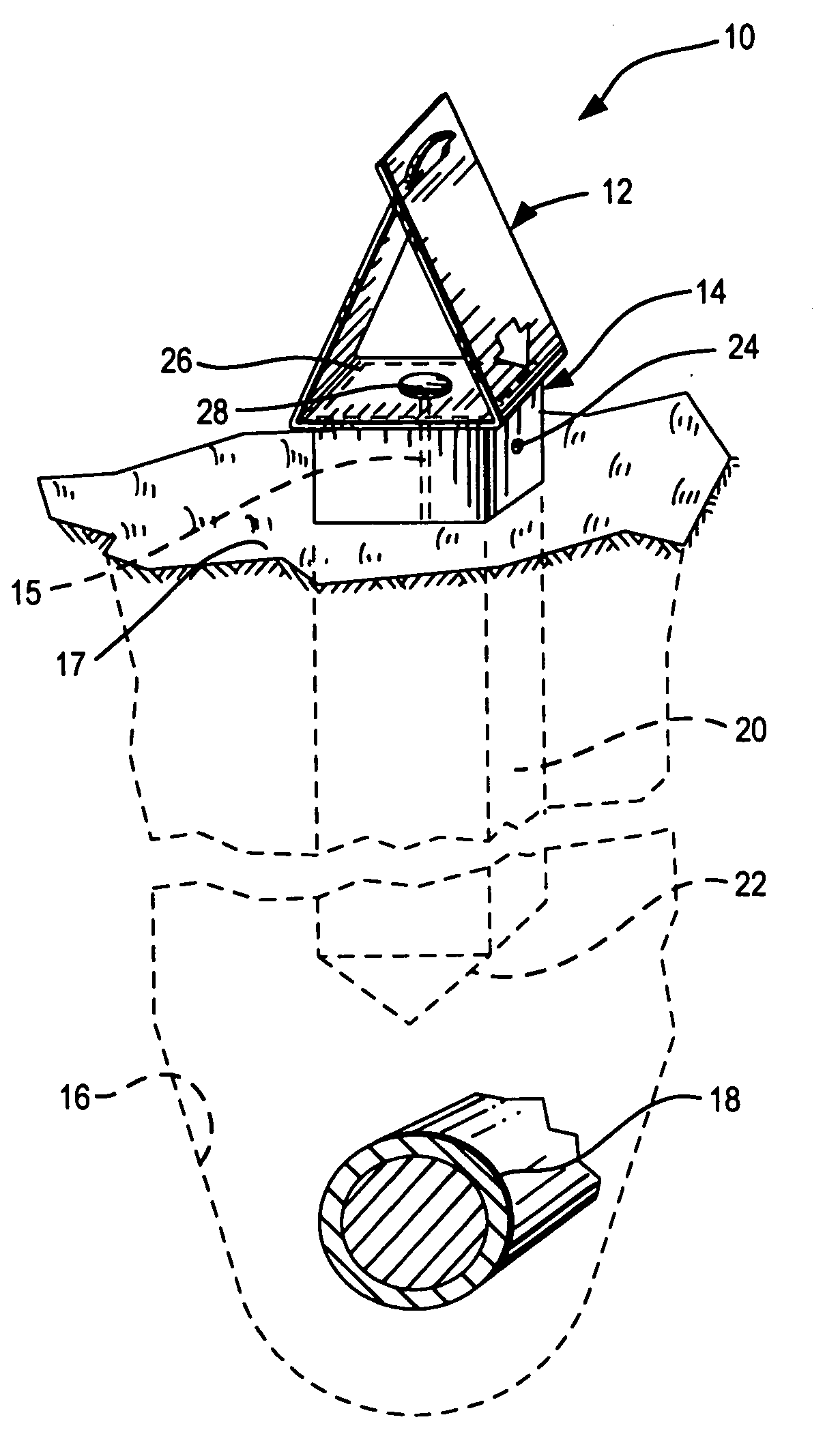
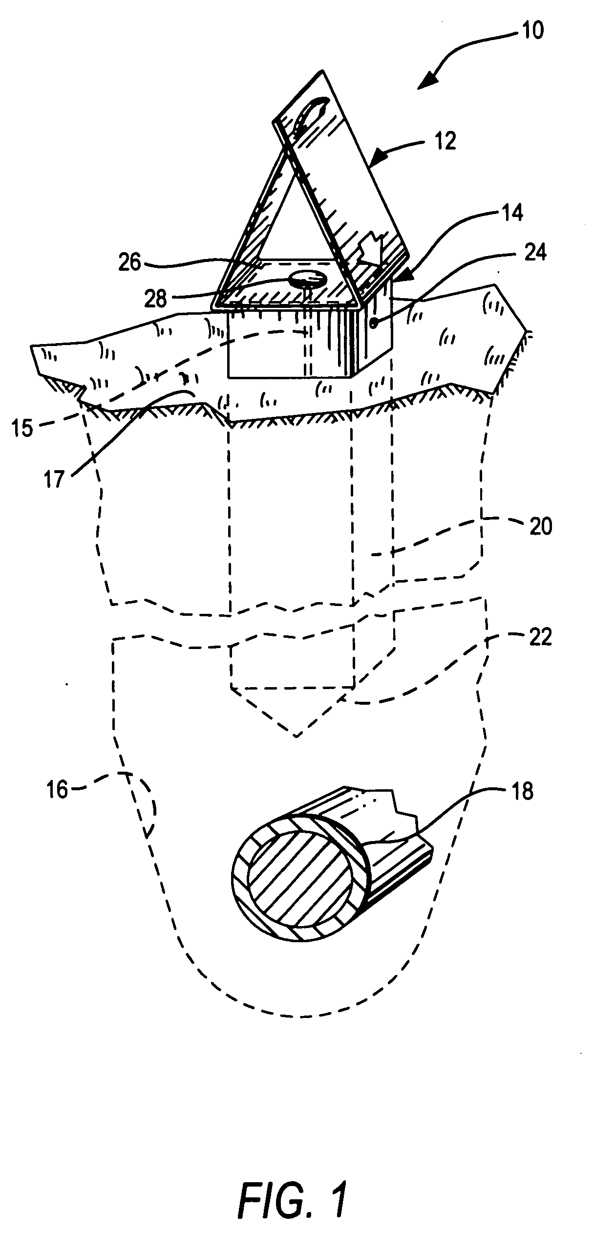
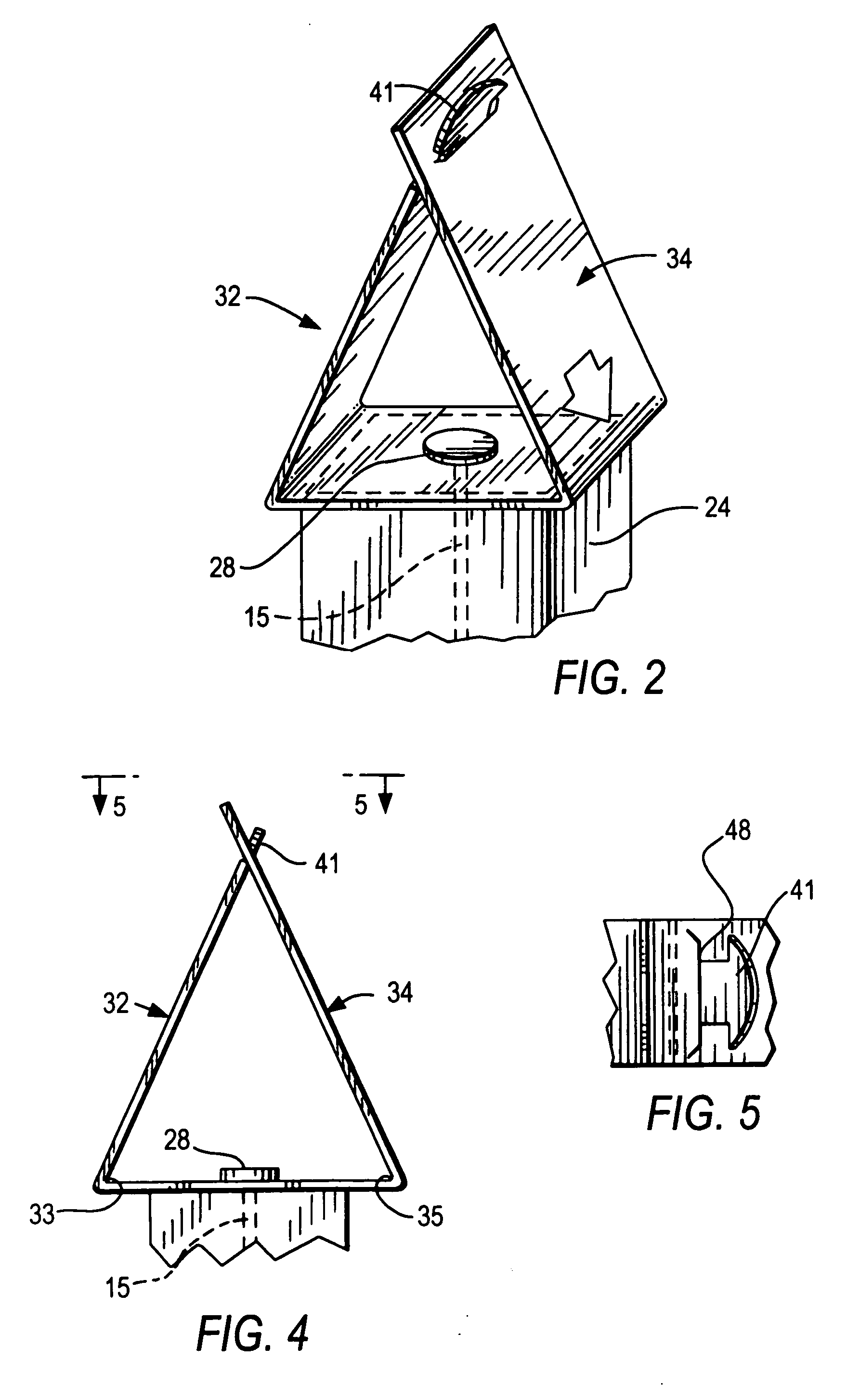
[0030]a. By using a first side portion 32, having an exterior display surface 36 with an identification sign 38, and by using a second side portion 34, having an exterior display surface 42 with an identification sign 44, the prior-art problem of not knowing the type of underground line being identified by the marker is avoided.

[0031]b. The marker 10 is flexible in the sense that it can be run over and will return to an upright position.

[0032]c. The marker 10a can use two or more ...


PUM


Abstract

A cable marker includes a flag for connection to a support stake, wherein the flag has a center portion for connection to the support stake and includes a first side portion having an exterior display surface for an identification sign and a second side portion having an exterior display surface for an identification sign. By using a first side portion having an exterior display surface with an identification sign and a second side portion having an exterior display surface with an identification sign, the problem of not knowing the type of underground line being identified by the marker is avoided.

Description

BACKGROUND OF THE INVENTION[0001]1. Field of the Invention[0002]This invention relates to an identification marker, and, more particularly, this invention relates to an identification marker, for a subterranean electrical cable or other conduit, having a display surface capable of receiving information.[0003]2. Description of the Prior Art[0004]Cable markers of the prior art include color-coded strands, commonly known as “whiskers”, and wooden support stakes to which the strands are nailed or otherwise attached, preferably in a vertical orientation. One problem with these cable markers is that it is difficult to know the type of underground line being identified, particularly when the color code of the strands is not known.OBJECTS AND SUMMARY OF THE INVENTION[0005]An object of the present invention is to provide an improved underground cable identification system.[0006]Another object of the present invention is to provide an improved underground cable identification system capable o...

Claims


Application Information

Patent Timeline
Patent Type & Authority Applications(United States)
IPC IPC(8): G01D21/00
CPCF16L1/11G01C15/04H02G2200/20H02G1/06H02G9/02G09F19/22
Inventor BURLANDO, ALBERT A.
Owner BURLANDO ALBERT A
Why Eureka
Try Eureka