
Compact Orthomode Transduction Device Optimized in the Mesh Plane, for an Antenna

a transducer device and orthomode technology, applied in waveguide horns, antennas, electrical devices, etc., can solve the problems of incompatibility between the size of the omts and the size of the mesh, the complexity of the complete antenna is much more complex, and the omts are still too larg

Active Publication Date: 2009-12-17
THALES SA
View PDF2 Cites 10 Cited by
  • Summary
  • Abstract
  • Description
  • Claims
  • Application Information

AI Technical Summary

Benefits of technology

The invention proposes an orthomode transducer device for an antenna that allows for the selective transfer of different modes of electromagnetic waves between a main guide and an auxiliary guide. The device includes a first and second auxiliary guides placed one above the other with parallel axes, and each has a window in relation to the main guide to allow for coupling of the modes. The second auxiliary guide can have a short-circuit and can be designed with different orientations. The invention also proposes an antenna and an array antenna equipped with the orthomode transducer device. The technical effects of the invention include improved mode coupling and more efficient energy utilization.

Problems solved by technology

In this case there is incompatibility between the size of the OMTs and that of the mesh.
The OMJ therefore has a space requirement in the plane of the mesh typically of around 2λ, which still proves to be too high.
In addition, the positioning of the ports then makes the architecture of the complete antenna much more complicated and has the effect of increasing the assessments of mass and size requirement.

Method used


Image

  • Compact Orthomode Transduction Device Optimized in the Mesh Plane, for an Antenna
  • Compact Orthomode Transduction Device Optimized in the Mesh Plane, for an Antenna
  • Compact Orthomode Transduction Device Optimized in the Mesh Plane, for an Antenna

Examples


Embodiment Construction

[0038]The object of the invention is to enable the production of orthomode transducer devices with optimized compactness, preferably without a decoupling vane (or septum) for a transmission and / or reception antenna (optionally of the array type).

[0039]In the following it will be assumed, by way of nonlimiting example, that the antenna is a direct radiation array (or DRA) antenna and, for example, is active. It therefore comprises an array of elementary radiation sources, such as horns for example, each coupled to an orthomode transducer device D according to the invention, and control means suitable for controlling, by means of (an) active system(s), the amplitude and / or phase of the radiofrequency signals to be transmitted (or in the reverse direction, received from space in the form of waves) by the elementary radiation sources according to a chosen diagram. However, the invention is not limited to this type of antenna. It in fact relates, on the one hand, to any type of DRA or ot...


PUM


Abstract

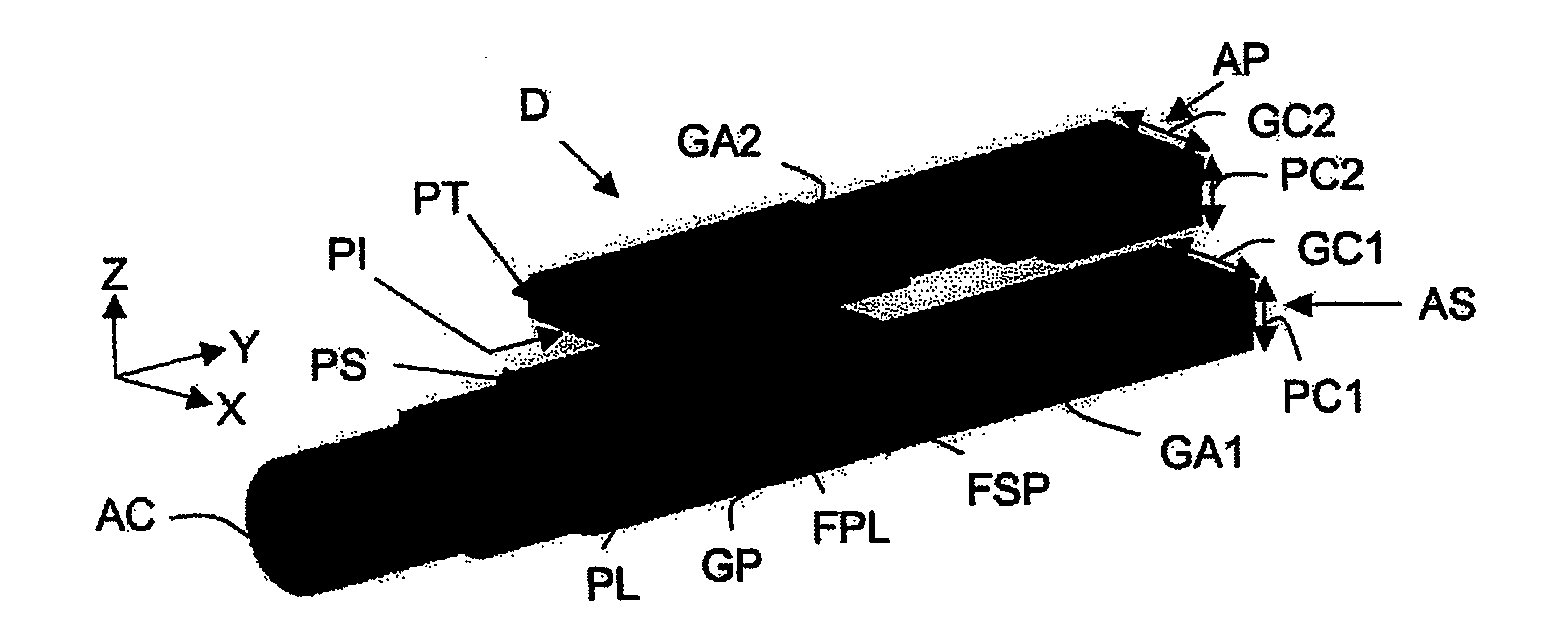
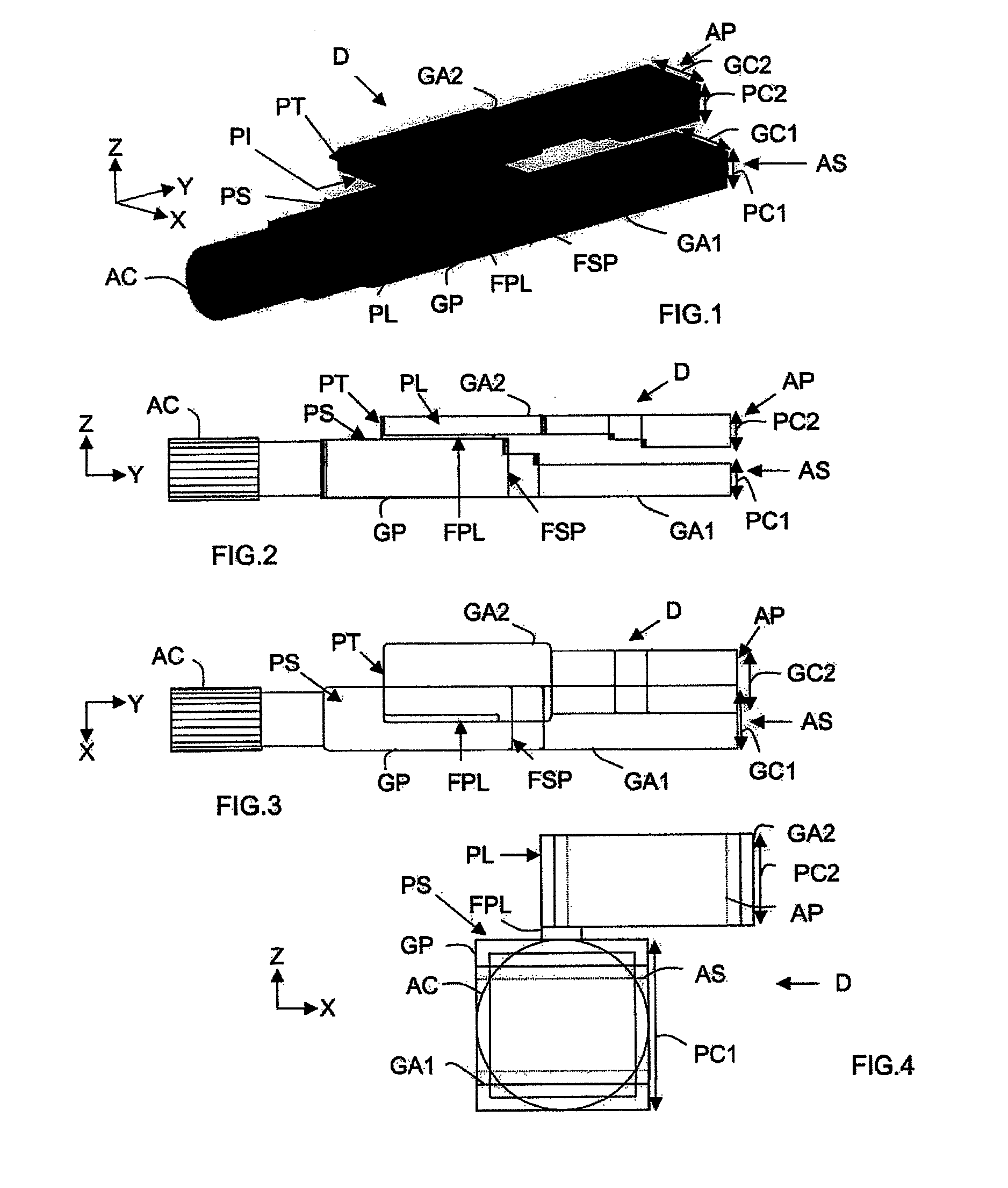
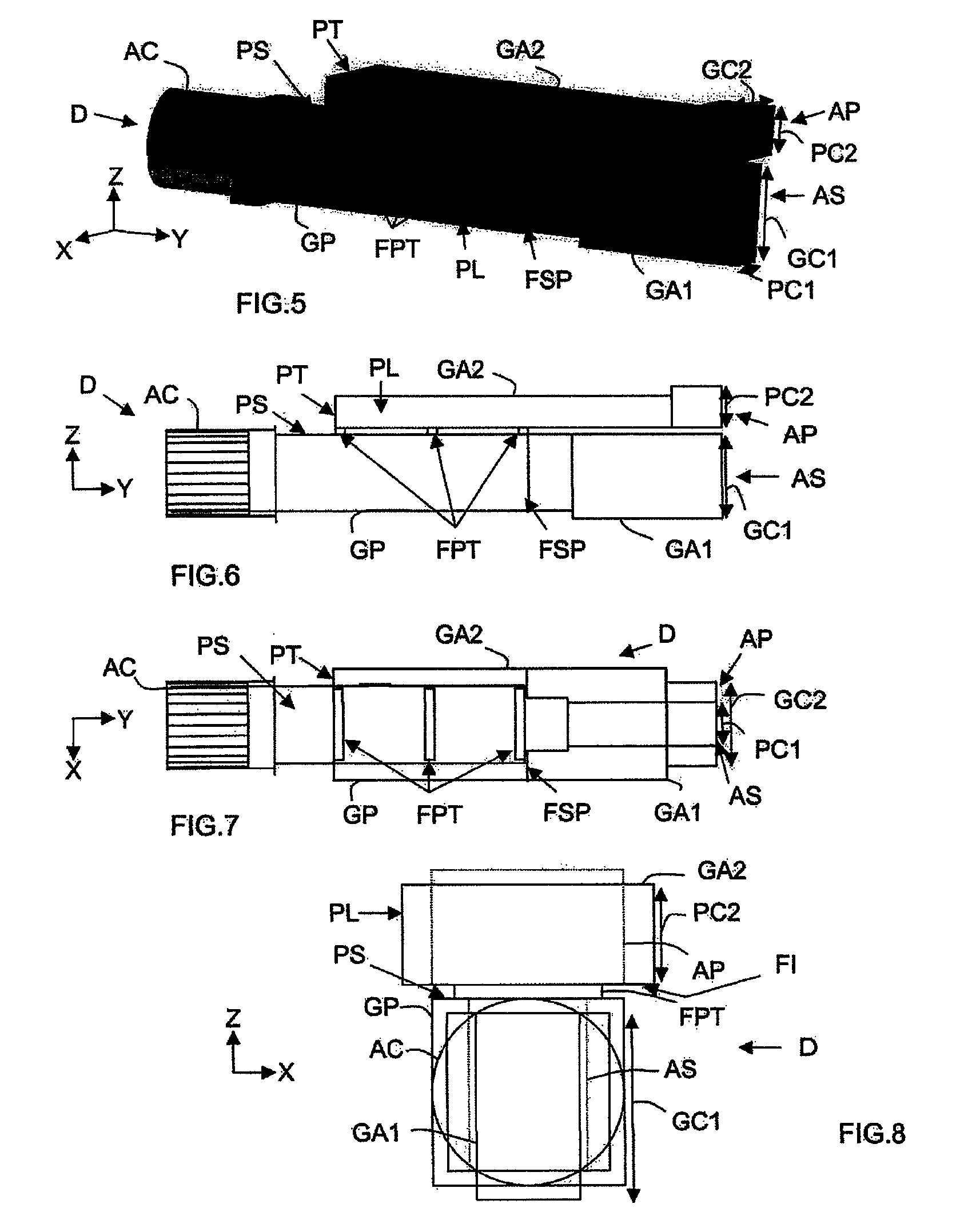
An orthomode transducer device (D), for an antenna, comprises (i) a main guide (GP) designed for the propagation along a main axis of first and second modes having polarizations orthogonal to each other and provided with a first end coupled to a circular port (AC) and a second end, (ii) a first auxiliary guide (GA1) designed for the propagation of the first mode along a first auxiliary axis and provided with a first end coupled in series to the second end of the main guide via a series window (FSP) and with a second end coupled to a series port (AS), and (iii) a second auxiliary guide (GA2) designed for the propagation of the second mode along a second auxiliary axis, coupled to the main guide via a parallel window (FPL) and provided with a first end coupled to a parallel port (AP). The first (GA1) and second (GA2) auxiliary guides are superposed. The parallel window (FPL) is defined between an upper wall (PS) of the main guide (GP) and a lower wall (PI) of the second auxiliary guide (GA2) and oriented in relation to the main axis so as to enable coupling of the main guide to the second auxiliary guide for the selective transfer of the second mode from one to the other, and so as to make the first mode propagate between the main guide and the first auxiliary guide.

Description

CROSS REFERENCE TO RELATED APPLICATIONS[0001]This is a national stage of International application PCT / EP2007 / 057797, filed Jul. 27, 2007, which claims priority of French application no. 0653180, filed Jul. 28, 2006, the disclosure of each application is incorporated herein by reference in its entirety.BACKGROUND OF THE INVENTION[0002]The invention relates to the field of transmitter and / or receiver antennas, optionally of the array type, and more particularly to orthomode transducer devices (or “transducers”) which equip such antennas.[0003]“Antenna” is here understood to mean both a single elementary radiation source coupled to an orthomode transducer device and an array antenna.[0004]Furthermore, an “array antenna” is here understood to mean an antenna that is able to function in transmission and / or in reception and comprising an array of elementary radiation sources and control means suitable for controlling, by means of (an) active system(s), the amplitude and / or the phase of t...

Claims


Application Information

Patent Timeline
Patent Type & Authority Applications(United States)
IPC IPC(8): H01P1/161H01P5/12
CPCH01P1/161H01Q21/064H01Q13/0258H01P1/16H01Q13/02H01Q21/06
Inventor GIRARD, THIERRYCHANE-KEE-SHEUNG, HARRYBOSSHARD, PIERRELAVAL, LAURENCE
Owner THALES SA
Learn More