Camera system for monitoring a space area

a camera system and space area technology, applied in the field of space area cameras, can solve the problems of requiring a comparatively high installation and mounting cost, affecting the safety of personnel or objects present in the region of automated installation, and limiting the flexibility of laser scanners, so as to achieve cost-effective and reliable mounting and installation, and simple and cost-effective

Active Publication Date: 2009-12-17
PILZ (COMPANY)
View PDF14 Cites 45 Cited by
  • Summary
  • Abstract
  • Description
  • Claims
  • Application Information

AI Technical Summary

Benefits of technology

[0009]Against this background, it is an object of the present invention to provide a mechanical concept that enables a simple and cost effective mounting of a camera system. In particular, it is an object to provide a mechanical concept that enables a cost effective and reliable mounting of a stereo camera system comprising at least two camera units.

Problems solved by technology

As a general problem, the automated sequence can constitute a danger to persons or objects present in the region of the automated installation.
However, light barriers, light grids, guard doors and safety gates are limited in their flexibility and require a comparatively high outlay on mounting and installation.
Laser scanners are somewhat more flexible, but still remain limited in their ability to distinguish between dangerous and safe situations.
However, such approaches place high requirements on the resolution and accuracy of the three dimensional image recording.
However, this reference does not provide any proposals for a stable and reliable mechanical design of such a camera system, which design ensures the required functional reliability and, moreover, enables cost effective mounting.
However, these camera systems are neither capable, nor envisaged for the purpose, of recording a three dimensional image of a space area in order to safeguard a dangerous installation as a function thereof.
In particular, these publications do not contain any proposals for integrating a number of cameras in a cost effective way and with a very high degree of accuracy to form a stereo camera system.

Method used


Image

  • Camera system for monitoring a space area
  • Camera system for monitoring a space area
  • Camera system for monitoring a space area

Examples


Embodiment Construction

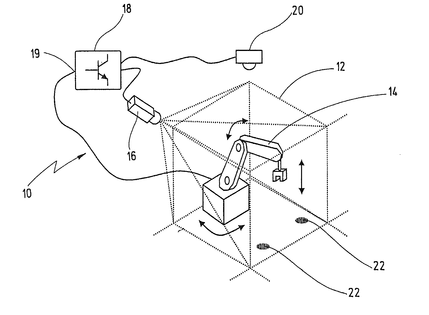
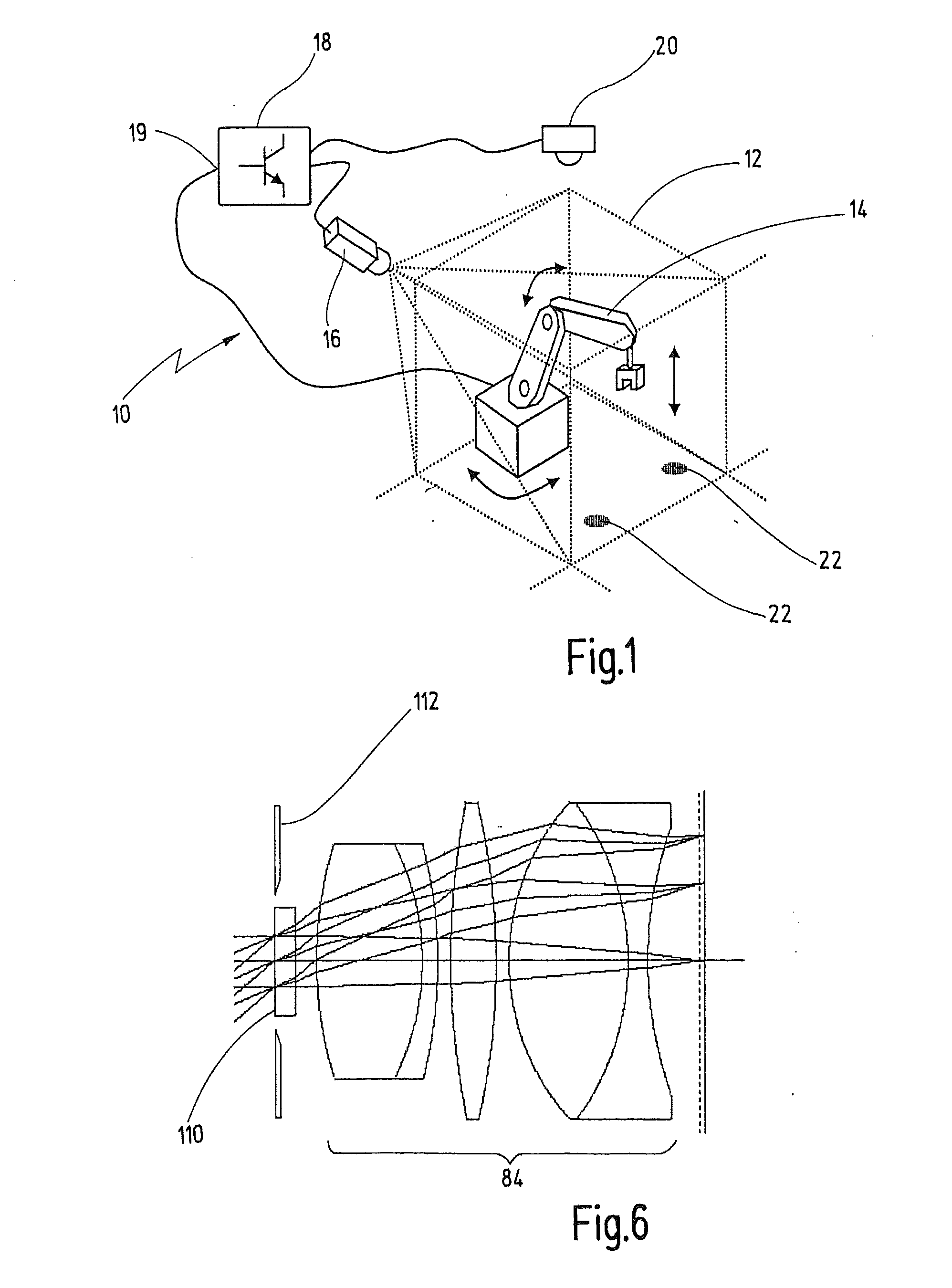
[0045]A device for safeguarding an automated installation in its entirety is designated in FIG. 1 by reference numeral 10. The device 10 monitors a space area 12 in which the automated installation, here a robot 14, is arranged. The device 10 includes a camera system 16 that is directed to the space area 12. The camera system 16 is connected to a controller 18. The controller 18 is designed to evaluate the images of the space area 12 that are recorded by means of the camera system 16, and to stop the robot 14 as a function thereof when a dangerous situation is detected. As an alternative to the illustration in FIG. 1, camera system 16 and controller 18 could also be integrated in a common housing, the controller 18 then using the camera images to generate a switching signal for switching off the installation 14 and to provide it at an output 19.

[0046]Reference numeral 20 designates a light source that can optionally be provided to illuminate the space area 12. In some exemplary embo...


PUM


Abstract

A camera system for monitoring a space area has a camera unit including an image sensor and a number of optical elements which form an imaging optics. A system body has at least one receptacle for the camera unit. A mounting part serves for aligning the system body relative to the space area. The optical elements are fastened on an objective body which has a mounting flange. The objective body is fastened in the receptacle by means of the mounting flange.

Description

CROSS REFERENCES TO RELATED APPLICATIONS[0001]This application is a continuation of international patent application PCT / EP2007 / 008893 filed on Oct. 12, 2007 designating the U.S., which international patent application has been published in German language and claims priority from German patent application DE 10 2006 050 235.3 filed on Oct. 17, 2006. The entire contents of these prior applications are incorporated herein by reference.BACKGROUND OF THE INVENTION[0002]The present invention relates to a camera system for monitoring a space area, and in particular to a camera system for safeguarding an automated installation arranged in such a space area.[0003]In many industrial and non-industrial applications, movement sequences and / or production processes are carried out in an automated fashion. As a general problem, the automated sequence can constitute a danger to persons or objects present in the region of the automated installation. For safeguarding purposes, use is typically made...

Claims


Application Information

Patent Timeline
Patent Type & Authority Applications(United States)
IPC IPC(8): H04N7/18
CPCF16M11/041F16M11/06F16M11/10F16M11/2014F16P3/144F16M13/027F16P3/14H04N5/2251F16M13/02H04N23/50
Inventor WENDLER, MARTIN
Owner PILZ (COMPANY)
Why Eureka
Try Eureka