Continuously variable transmission

a transmission and continuous variable technology, applied in the direction of instruments, machines/engines, gearing, etc., can solve the problems of oversizing of accessories, wasting energy during operation, and accessory speed not operating within the maximum efficiency speed rang

Inactive Publication Date: 2009-12-17
FALLBROOK INTPROP COMPANY
View PDF100 Cites 119 Cited by
  • Summary
  • Abstract
  • Description
  • Claims
  • Application Information

AI Technical Summary

Problems solved by technology

However, it is often the case that the optimum operating speed of the driven device is not the same as the optimum operating speed of the power source.
The result of such system configuration is that often any given accessory does not operate within its maximum efficiency speed range.
Consequently, inefficiencies arise from wasted energy during operation and oversizing of the accessories to handle the speed and / or torque ranges.

Method used


Image

  • Continuously variable transmission
  • Continuously variable transmission
  • Continuously variable transmission

Examples


Embodiment Construction

” one will understand how the features of the systems and methods provide several advantages over known systems and methods.

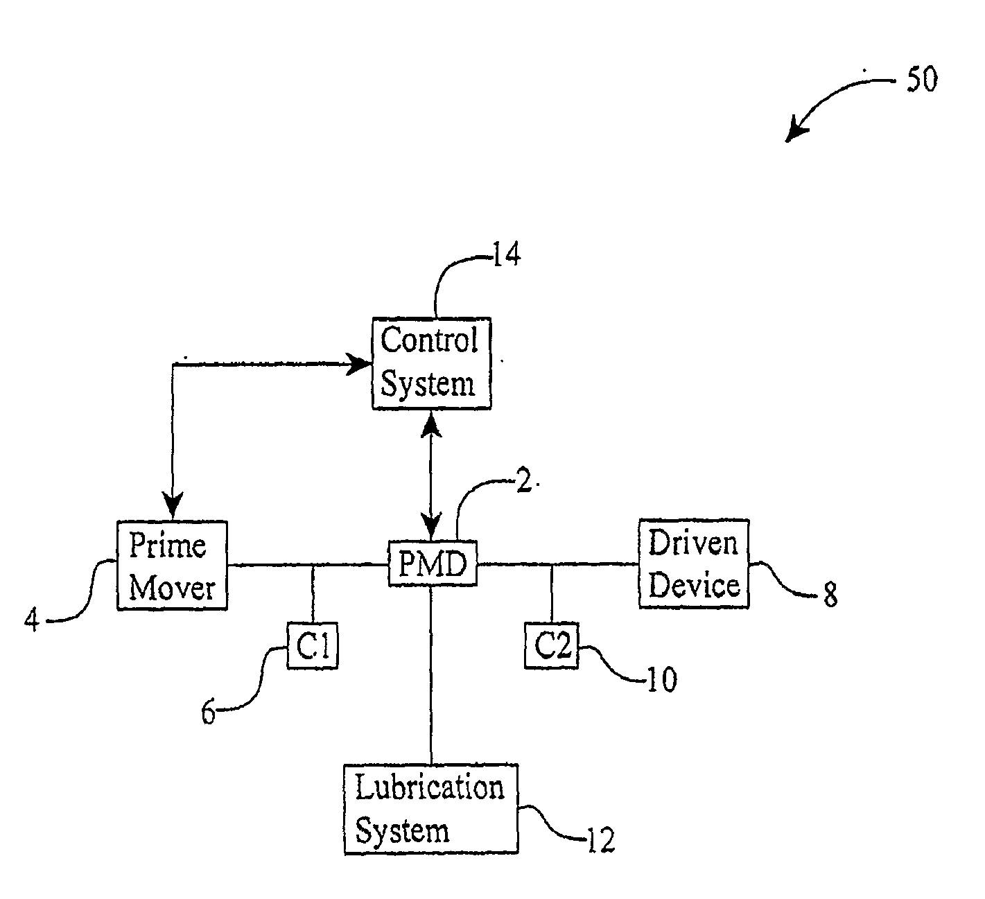
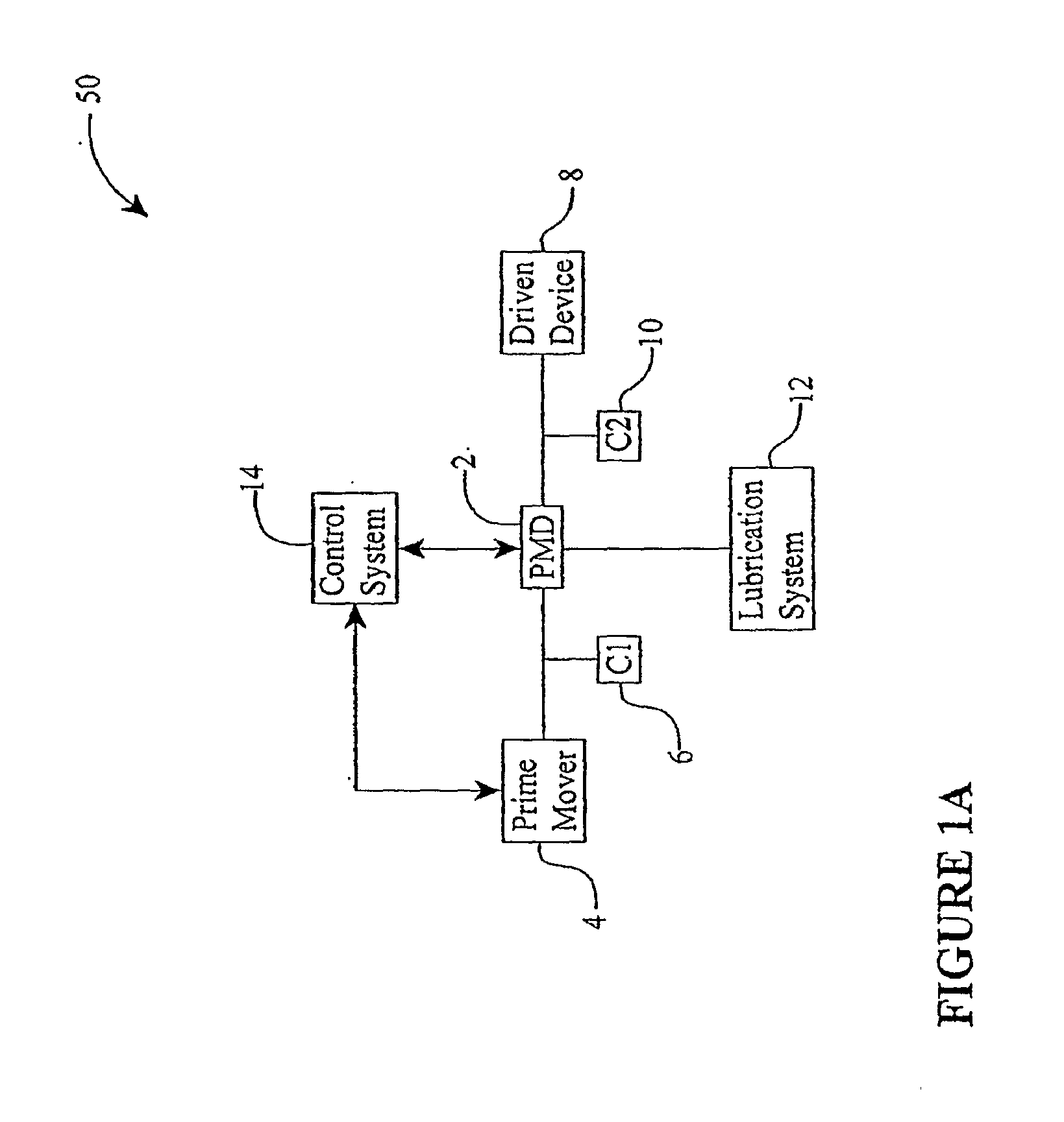
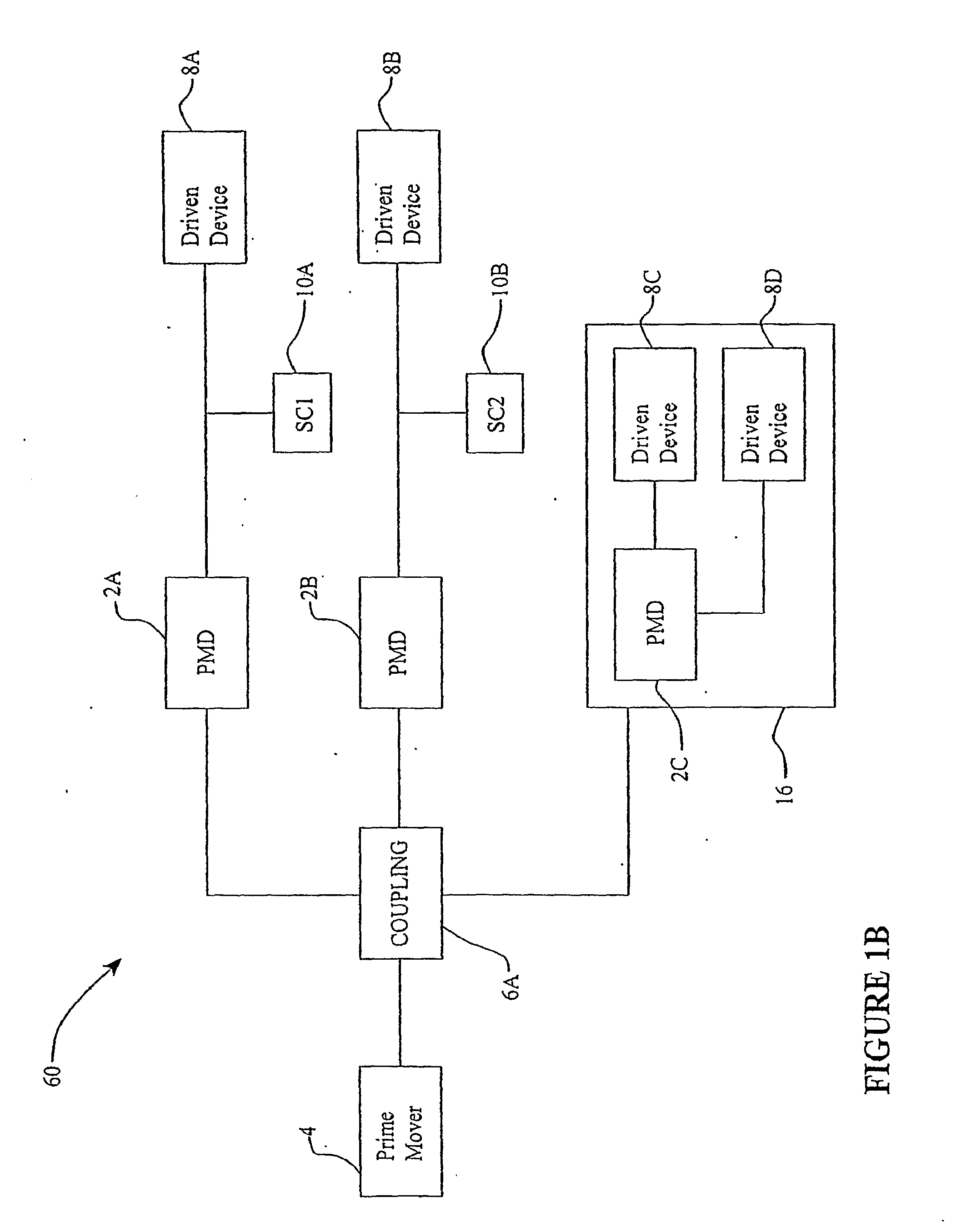
[0009]One aspect of the inventive embodiments is directed to a compound power modulating device as generally shown in FIGS. 15A-20. Another feature of the inventive embodiments covers a power modulating device as generally shown in FIGS. 2A-2D, 3-4, 10, 13-14. Yet another aspect of the inventive embodiments concerns a power modulated drivetrain as generally shown in FIGS. 1A, 1B, or 21-22. inventive embodiments are also directed to devices, assemblies, subassemblies, components, and / or methods as generally illustrated in FIGS. 1A-27B and described in the specification.

[0010]In one embodiment, the invention relates to a front end accessory drive (FEAD), for an automotive engine having a crankshaft. The FEAD can include a power modulating device mounted on the crankshaft, wherein an accessory operationally couples to the power modulating device. The power modulat...


PUM


Abstract

Embodiments are directed to a front end accessory drive (FEAD), subassemblies, and components therefor. Embodiments disclosed cover power modulating devices (PMD) which can be used in a FEAD. In one embodiment, a continuously variable transmission (CVT) is coupled directly to a crankshaft of a prime mover, and the CVT is used to regulate the speed and / or torque delivered to an accessory. A compound drive device includes a motor / generator subassembly cooperating with a CVT subassembly to provide a motor functionality with torque multiplication or division, or alternatively, a generator functionality with torque multiplication or division. In some embodiments, a FEAD includes a PMD having a sun shaft configured to couple to a sun of the PMD and to an electric motor component, such as an electrical armature or an electrical field. In one embodiment, the electrical armature the electrical field are placed concentrically and coaxially and configured to rotate relative to one another in opposite directions.

Description

RELATED APPLICATIONS[0001]This application claims the benefit of, and hereby incorporates by reference herein in its entirety, U.S. Provisional Application 60 / 816,713, filed on Jun. 26, 2006.BACKGROUND OF THE INVENTION[0002]1. Field of the Invention[0003]The field of the invention relates generally to mechanical and / or electro-mechanical power modulation devices and methods, and more particularly to continuously and / or infinitely variable, planetary power modulating devices and methods for modulating power flow in a power train or drive, such as power flow from a prime mover to one or more auxiliary or driven devices.[0004]2. Description of the Related Art[0005]In certain systems, a single power source drives multiple devices. The power source typically has a narrow operating speed range at which the performance of the power source is optimum. It is preferred to operate the power source within its performance optimizing operating speed range. A driven device typically also has a nar...

Claims


Application Information

Patent Timeline
Patent Type & Authority Applications(United States)
IPC IPC(8): B60W10/10F16H37/00G06F19/00
CPCF01B2009/045Y10T477/619F16H15/50F02B67/04F16H15/28F16H15/52F16H13/08F16H57/04F16H57/0427F16H57/0421F16H57/0431F16H57/0428F16H57/0484F16H61/32F16H61/6646F16H2061/6644
Inventor POHL, BRAD P.MILLER, DONALD C.SMITHSON, ROBERT A.CARTER, JEREMYLOHR, CHARLES B.
Owner FALLBROOK INTPROP COMPANY
Why Eureka
Try Eureka