Composite profile for window, door or facade element

a technology for facade elements and composite profiles, applied in the direction of doors/windows, building components, door/window fittings, etc., can solve the problems of poor workability of thermosetting synthetic materials, difficult to properly cut thermosetting synthetic materials, steel brackets or other metal bridges, etc., to improve the thermal separation of outer profile parts, improve the insulating characteristics of composite profiles, and improve fire resistance properties of composite profiles

Inactive Publication Date: 2009-12-24
TECHNOFORM BAUTEC HLDG
View PDF47 Cites 23 Cited by
  • Summary
  • Abstract
  • Description
  • Claims
  • Application Information

AI Technical Summary

Benefits of technology

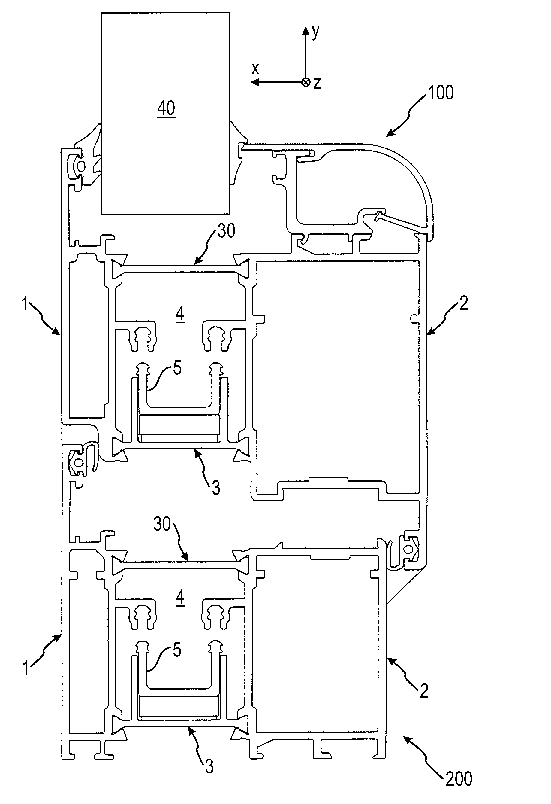
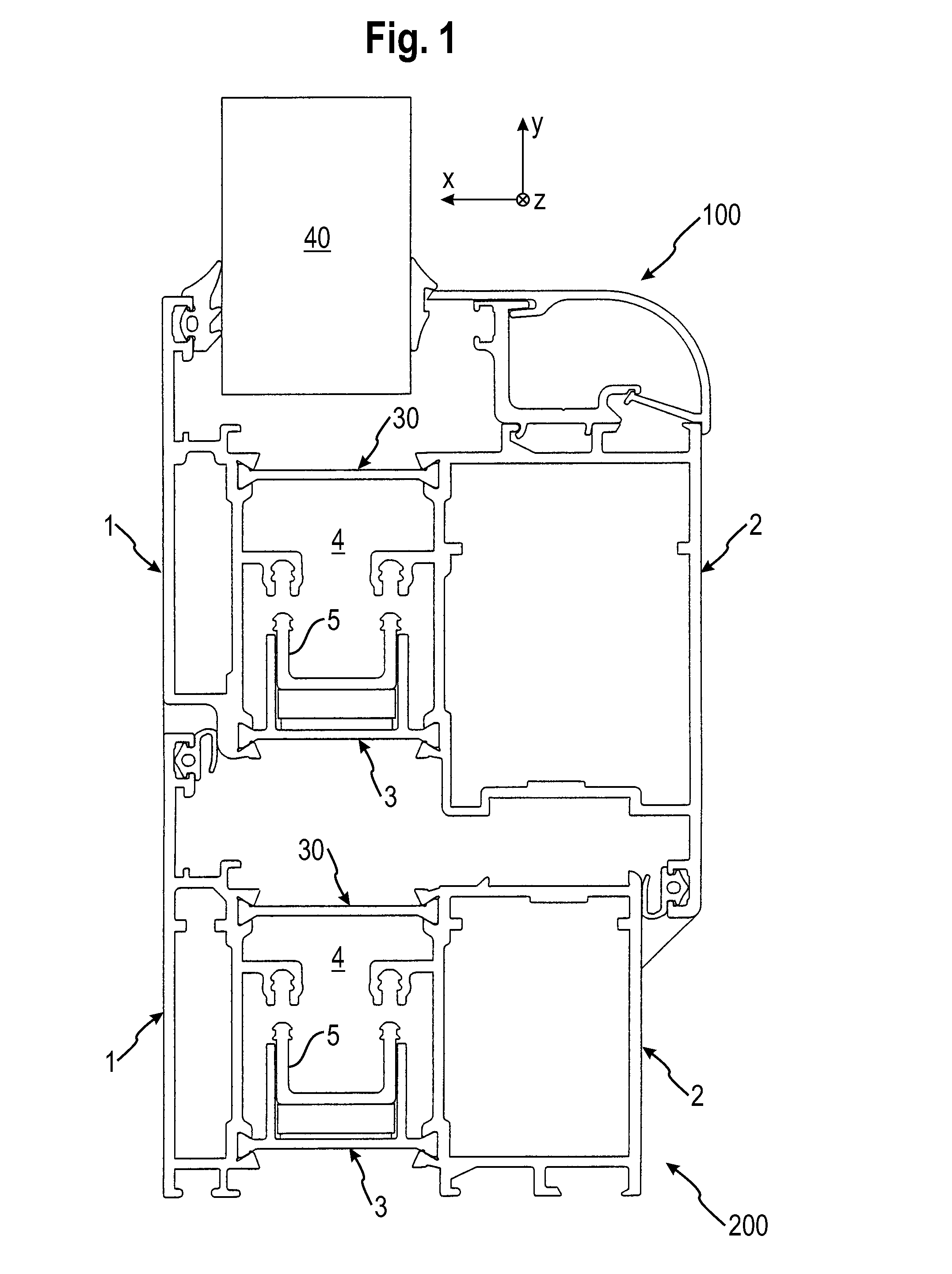
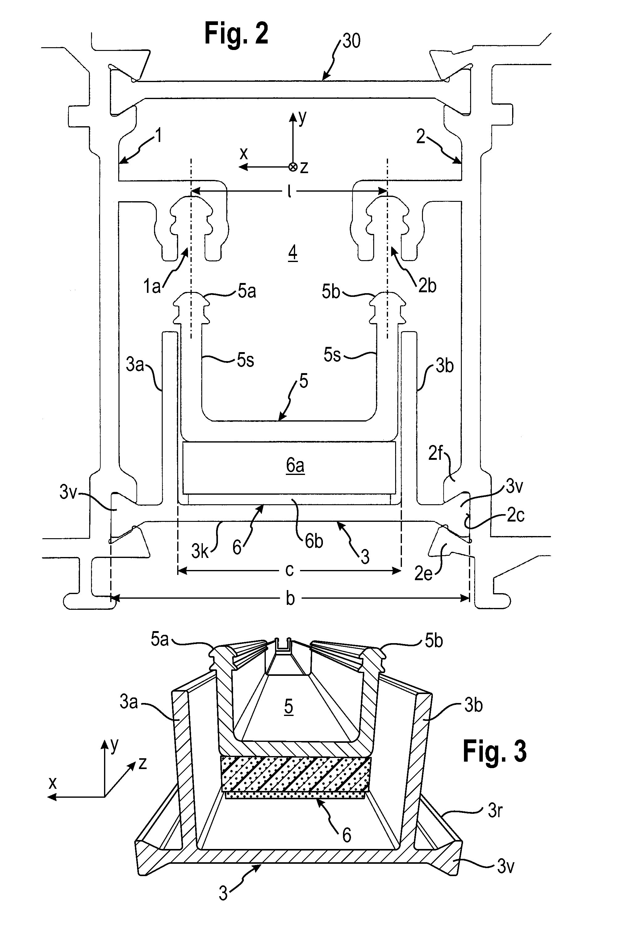
[0018]By providing the actuating element, which is activated by the heat generated in case of a fire, and by actively moving the outer profile part connecting element into engagement with the outer profile parts upon activation of the actuating element, a secure connection of the outer profile parts in the case of fire, as well as a defined conductivity of heat from the fire side to the side facing away from the fire, are ensured. Furthermore, the active movement of the outer profile part connecting element into the engagement position makes it possible to dispose the outer profile part connecting element so as to be spaced or separated from the outer profile parts during normal usage. This separation means that the outer profile part connecting element does not conduct heat across the intermediate space of the composite profile during normal usage, thereby improving the thermal separation of the outer pr...

Problems solved by technology

However, thermosetting synthetic materials have the disadvantage of poor workability.
Thermosetting synthetic materials, in particular, are difficult to cut properly when the composite profile must be sawed into segments of specific lengths during the finishing process.
The use of steel brackets or other metal bridges has the disadvantage of requi...

Method used


Image

  • Composite profile for window, door or facade element
  • Composite profile for window, door or facade element
  • Composite profile for window, door or facade element

Examples


Embodiment Construction

[0024]Representative, non-limiting examples of the present invention will now be described in further detail with reference to the attached drawings. This detailed description is merely intended to teach a person of skill in the art further details for practicing preferred aspects of the present teachings and is not intended to limit the scope of the invention. Furthermore, each of the additional features and teachings disclosed below may be utilized separately or in conjunction with other features and teachings to provide improved composite profiles and insulating strips, as well as methods for using the same.

[0025]Moreover, combinations of features and steps disclosed in the following detail description may not be necessary to practice the invention in the broadest sense, and are instead taught merely to particularly describe representative examples of the invention. Furthermore, various features of the above-described and below-described representative examples, as well as the va...


PUM


Abstract

A composite profile for a window, door or façade element includes first and second outer profile parts and at least one insulating strip connecting the first and second outer profile parts with an intermediate space defined between them for thermal separation. At least one outer profile part connecting element is disposed in the intermediate space so that it is normally not in contact with the first and second outer profile parts. An actuating element is disposed so that, upon being activated by heat, it moves the outer profile part connecting element into engagement with the first and second outer profile parts, so that the outer profile part connecting element connects the first and second outer profile parts.

Description

CROSS-REFERENCE[0001]The present application claims priority to European patent application number 08 011 031.5, filed Jun. 18, 2008, the contents of which are fully incorporated herein by reference.TECHNICAL FIELD[0002]The present invention relates to a composite profile for a window, door or façade element, which preferably have predetermined fire resistance properties, and to an apparatus for connecting profile or frame parts of such a composite profile.BACKGROUND ART[0003]Industrial buildings and office buildings are typically designed so as to be subdivided into ‘fire compartments’ in order to provide passive fire protection for limiting or retarding the spread of fire, smoke, poisonous gases and / or damaging heat in case of a fire. For this purpose, the doors and windows that are utilized in the building must have predetermined fire resistance properties, which are ascertained by performing a standard fire resistance test on the structural element. According to the results of t...

Claims


Application Information

Patent Timeline
IPC IPC(8): E04C2/38
CPCE06B3/26303E06B3/5828E06B2003/26394E06B2003/26387E06B2003/2633Y10S49/01
Inventor SIODLA, THORSTEN
Owner TECHNOFORM BAUTEC HLDG
Why Eureka
Try Eureka