
Waste concrete and aggregate reclaimer

a reclaimer and aggregate technology, applied in the direction of liquid displacement, multi-stage water/sewage treatment, separation process, etc., can solve the problems of large settling pond, environmental concern, and high cost, and achieve the effect of increasing the effective separation surface, increasing the effective separation area for flotation and sedimentation, and increasing the effective separation area

Inactive Publication Date: 2009-12-24
SP ZICOM PTE LTD
View PDF21 Cites 5 Cited by
  • Summary
  • Abstract
  • Description
  • Claims
  • Application Information

AI Technical Summary

Benefits of technology

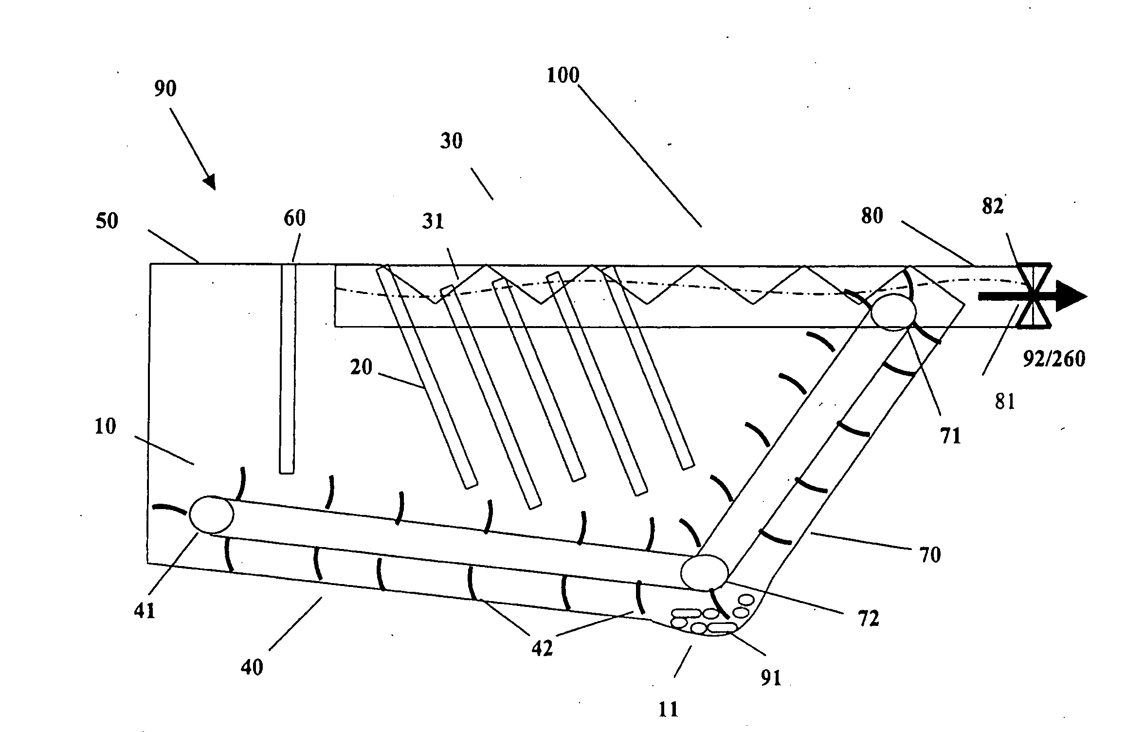
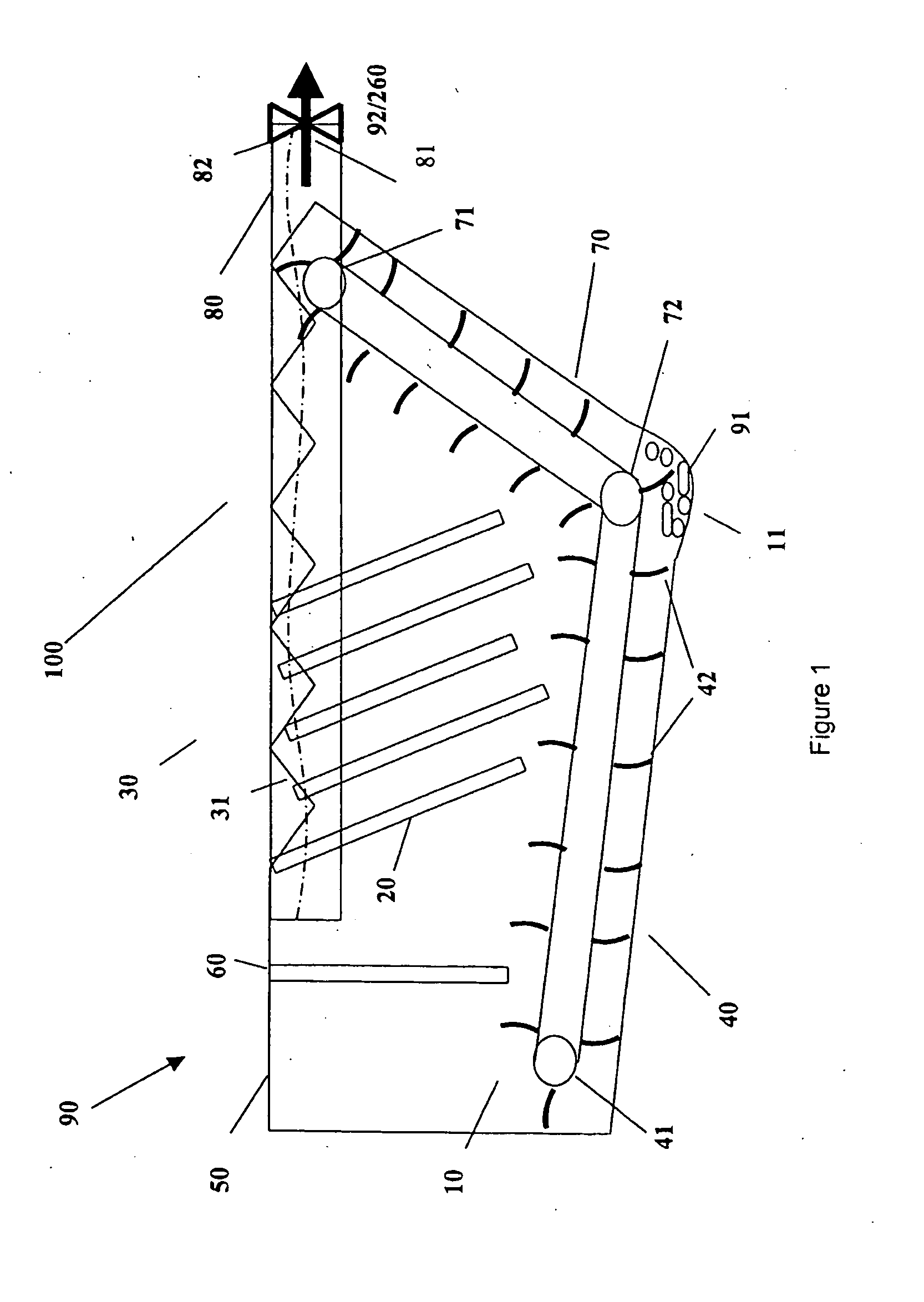
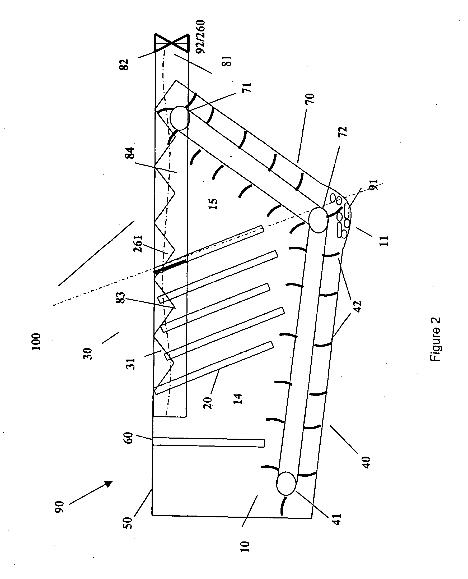
[0018]In an embodiment of the invention, it is to be appreciated that the lamella plates increase the effective separation surface such that its maximum admissible hydraulic load is higher than that used in traditional reclaimer systems. The final distributed solids 91 form both larger concrete aggregates on the lower side of the lamella plates, and fines 92 on the upper side of the lamella plates. Thus, with the use of the lamella plates, short settling is achieved, as the effective separation area for flotation and sedimentation is increased.
[0019]In a preferred embodiment, the level of agitation, imparted by the agitation mechanism, can be controlled by a user. The purpose of this agitation mechanism is to agitate the solid aggregates and slurry water, to impart enough velocity to the solid laden slurry water to be above the settling velocity of the particles in the slurry water. Thus, there is no need for space consuming settling ponds. It can thus be appreciated that a higher agitation will impart a higher velocity. This will allow finer particles, with lower settling velocities in the solid laden slurry water to be agitated and rise up, and not settle at the bottom of the reclaiming tank. Thus, by controlling the level of agitation by adjusting the velocity of the agitation mechanism, a user will be able to control the size of particles that are to be settled at the bottom of the reclaiming tank.
[0024]In yet another preferred embodiment of the present invention, the reclaimer further includes a baffle plate to contain the turbulence that may be imparted when the solid laden slurry water is introduced into the reclaiming tank. This allows a larger hydraulic load to be introduced into the tank, without the need to meticulously meter the input into the tank.

Problems solved by technology

In the concrete batching industry, disposal of excess concrete, waste concrete and the washing of mixer trucks and plants create an environmental concern, and is a costly one.
However, for effective settling to occur, large settling ponds are required.
This is undesirable in land scarce areas, for example, Singapore.
Furthermore, since the screen must slope downwardly and because a relatively long length of screen is required for effective separation, the head of suspension required at the top of the screen is relatively large.
Further, such reclaimers may also allow too much product into the screens, as there is no way to regulate the flow of the product through the static screens.
However, this type of screening, depending on the size of the solids, can either pass thro ugh the perforations with the liquid, or clog the perforations.
Screw type conveyor reclaimers are inefficient because they work against the force of gravity.
Further, these types of reclaimers provide limited hydraulic capacity in that they are unable to take multiple truckloads of solid laden slurry water.
This type of system is also inefficient in that the rotating screw needs to take into account the weight of the individual buckets on the screws.
However, the addition of these chemicals and additives may alter the quality of the reclaimed material and liquids, and hence, is also undesirable.

Method used


Image

  • Waste concrete and aggregate reclaimer
  • Waste concrete and aggregate reclaimer
  • Waste concrete and aggregate reclaimer

Examples


Embodiment Construction

[0043]Reference will now be made in detail to the preferred embodiments of the invention, examples of which are illustrated in the accompanying drawings. The preferred embodiments of the invention are not intended to limit the invention in its broadest aspect to these embodiments. On the contrary, the invention is intended to cover alternatives, modifications and equivalents, which may be included within the spirit and scope of the invention as defined by the appended claims. Furthermore, in the following detailed description of the embodiments, numerous specific details are set forth in order to provide an understanding of the present embodiments.

[0044]Referring to the drawings, an embodiment of a solid matter separation apparatus in the form of a reclaimer 100 is seen in FIG. 1. The reclaimer 100 includes a reservoir in the form of a reclaiming tank 10, which is preferably inclined. However, it is to be understood that it is not an essential feature of the invention for the base o...


PUM

PropertyMeasurementUnit
angleaaaaaaaaaa
angleaaaaaaaaaa
sizeaaaaaaaaaa

Abstract

A reclaimer, for the separation of heavier solids from slurry water, including an inlet means (50) to allow loading of a flow of the solid laden slurry water (90), a reclaiming tank (10) to contain the input from the inlet means (50), a plurality of lamella plates (20) to increase the effective separation surface area to improve the separation process, said lamella plates (20) provided at an angle, an agitation mechanism (40) for loosening up the slurry water from the heavier solids, an outlet means (82) to allow the separated slurry water to exit the tank (10), wherein the agitation mechanism (40) is a conveyor, with a plurality of protrusions (42).

Description

FIELD OF INVENTION[0001]This invention relates to a method and apparatus of reclaiming solid aggregates from slurry water, and preferably removing fines from slurry water, resulting in clarified water. This invention has particular but not exclusive application in the concrete batching industry, and may be applicable in cases where the separation of solids from liquids is desired.BACKGROUND OF THE INVENTION[0002]In the concrete batching industry, disposal of excess concrete, waste concrete and the washing of mixer trucks and plants create an environmental concern, and is a costly one.[0003]Settling ponds have been traditionally used to separate solids from liquids. Solid laden slurry water to be disposed is discharged into a first pond for initial separation. At a second pond, further residual materials settle out, leaving clarified water to be transferred to a third pond. This system allows heavier material to be separated through gravitational settling. These solids are then event...

Claims


Application Information

Patent Timeline
Patent Type & Authority Applications(United States)
IPC IPC(8): B01D21/08
CPCB01D21/0018B01D21/0048B01D21/0066B01D21/2433B01D21/20B01D21/2427B01D21/2455B01D21/02B03B5/66
Inventor NG, KHEE YANGWONG, SAMUELLOW, GIAU LEONGNG, WEI LENGSIM, GIOK LAK
Owner SP ZICOM PTE LTD
Learn More