Breathing circuit with embedded acoustic reflectometer

a technology of acoustic reflectometer and a breathing circuit, which is applied in the field of breathing circuits and to acoustic reflectometers, can solve the problems of delay in the notice of a sudden obstruction and increase labor

Inactive Publication Date: 2009-12-24
UNIV OF SOUTHERN CALIFORNIA
View PDF6 Cites 14 Cited by
  • Summary
  • Abstract
  • Description
  • Claims
  • Application Information

AI Technical Summary

Benefits of technology

[0010]The gas valve may have an open position at which the valve does not cause a substantial disruption in acoustic

Problems solved by technology

Although related, an acoustic reflectometer is not usually used at the same time as a breathing circuit because the components of the acoustic reflectometer may be adverse

Method used


Image

  • Breathing circuit with embedded acoustic reflectometer
  • Breathing circuit with embedded acoustic reflectometer
  • Breathing circuit with embedded acoustic reflectometer

Examples


Embodiment Construction

[0035]Illustrative embodiments are now discussed. Other embodiments may be used in addition or instead. Details that may be apparent or unnecessary may be omitted to save space or for a more effective presentation. Conversely, some embodiments may be practiced without all of the details that are disclosed.

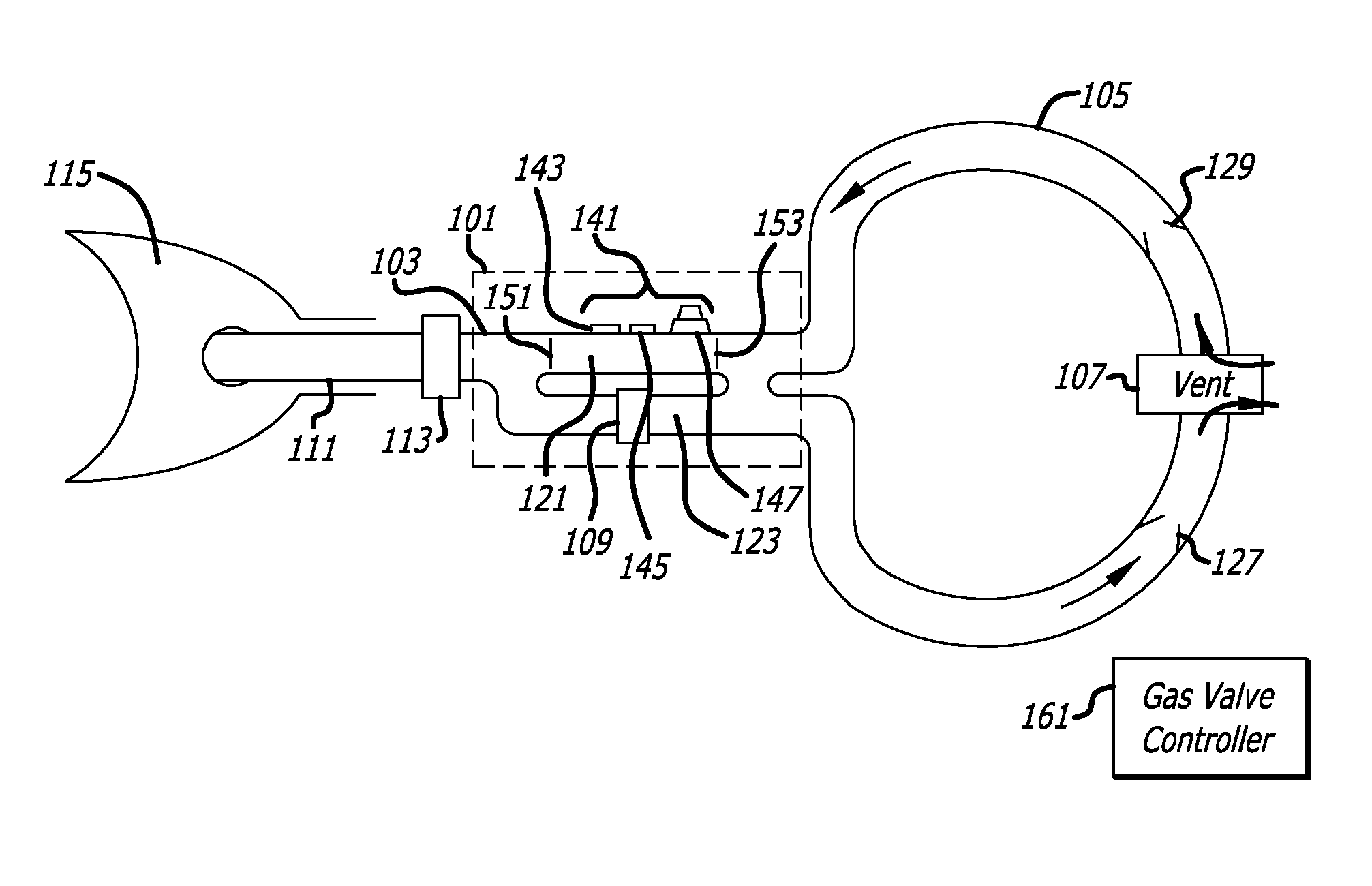
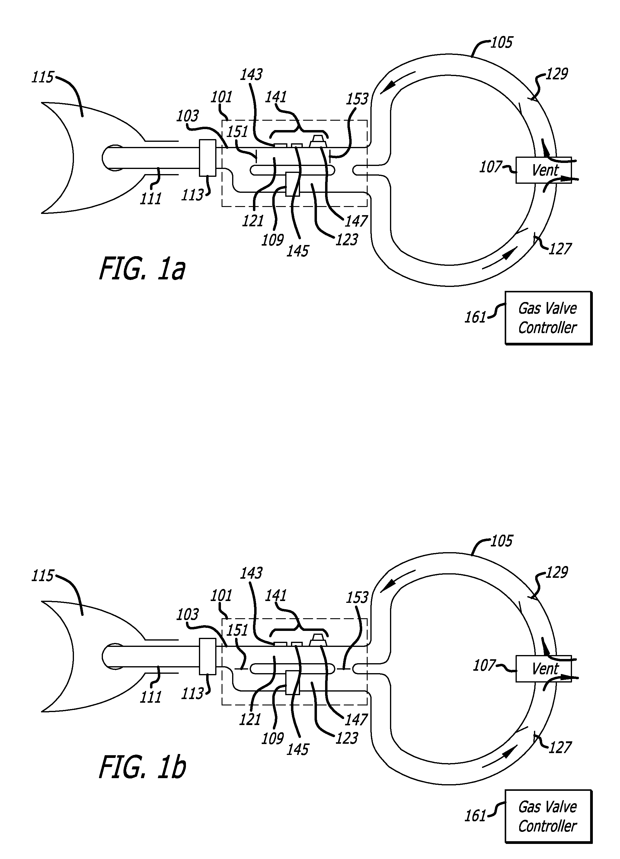
[0036]FIG. 1(a) illustrates an instrument for continuously monitoring acoustic reflections from within and / or beyond an intubation tube positioned within the mouth of a patient while the patient is breathing. The instrument is in a inactive state. FIG. 1(b) illustrates the instrument in FIG. 1(a) in an active state.

[0037]As illustrated in FIGS. 1(a) and (b), the instrument may include a valve and channel arrangement 101, a neck 103, a circular channel 105, a vent 107, and a humidifier 109. The neck 103 may be detachably coupled to an intubation tube 111 using a detachable coupling 113.

[0038]The intubation tube 111 may be positioned within a mouth of a patient while the patient is b...


PUM


Abstract

An instrument may continuously monitoring acoustic reflections from within and/or beyond an intubation tube positioned within the mouth of a patient while the patient is breathing. The instrument may include an acoustic reflectometer configured to detect the acoustic reflections. An acoustic flow channel may contain the acoustic reflectometer within it. The acoustic flow channel may be configured to acoustically couple the acoustic reflectometer to an end of the intubation tube, but to substantially block the free flow of expiratory gas from the end of the intubation tube through the acoustic flow channel. A gas flow channel may be separate from the acoustic flow channel and may be configured to allow the free flow of expiratory gas from the end of the intubation tube through the gas flow channel.

Description

CROSS-REFERENCE TO RELATED APPLICATION(S)[0001]This application is based upon and claims priority to U.S. Provisional Patent Application No. 61 / 074,290, entitled “Modified Breathing Circuit For Acoustic Reflectometry,” filed Jun. 20, 2008, attorney docket number 028080-0358. The entire content of this application is incorporated herein by reference.BACKGROUND[0002]1. Technical Field[0003]This disclosure relates to breathing circuits and to acoustic reflectometers.[0004]2. Description of Related Art[0005]Acoustic reflectometers are used to detect obstructions in intubation tubes and in cavities beyond them. Breathing circuits are used to assist a patient with breathing.[0006]Although related, an acoustic reflectometer is not usually used at the same time as a breathing circuit because the components of the acoustic reflectometer may be adversely affected by the humidity, pressure and / or temperature of expiratory gas in the breathing circuit. Instead, acoustic reflectometers are typic...

Claims


Application Information

Patent Timeline
IPC IPC(8): A61B8/12A61M16/20
CPCA61M16/0875A61M16/16A61M16/20A61M16/208A61M2016/0027A61M2016/0039A61M16/201A61M2016/103A61M2205/3375A61M2230/432A61B8/00A61M16/108A61M2016/0042A61M16/202A61M16/04
Inventor RAPHAEL, DAVID T.
Owner UNIV OF SOUTHERN CALIFORNIA
Why Eureka
Try Eureka