Optimized Message Format for Synchronization Flows Between Transaction Processing Systems

Inactive Publication Date: 2009-12-24
IBM CORP
View PDF11 Cites 1 Cited by
  • Summary
  • Abstract
  • Description
  • Claims
  • Application Information

AI Technical Summary

Benefits of technology

[0011]FIG. 3 is a block diagram of high level components comprising a

Problems solved by technology

Failures of such systems or of the connections between them can result in work in progress being left in an incomplete state.
In busy systems there can be large numbers of transactions that may need to be synchronized in this way after a failure or outage.
Network costs may then form a significant part of the processing overhead and may result in further delays to a connection being placed back into service while a synchronization of the transaction is attempted.
A transaction processing system normally processes each outstanding global transaction in sequence, incurring network costs for each one.
Therefore, as the number of transactions requiring synchronization increases, so does the corresponding network overhead.

Method used


Image

  • Optimized Message Format for Synchronization Flows Between Transaction Processing Systems
  • Optimized Message Format for Synchronization Flows Between Transaction Processing Systems
  • Optimized Message Format for Synchronization Flows Between Transaction Processing Systems

Examples


Embodiment Construction

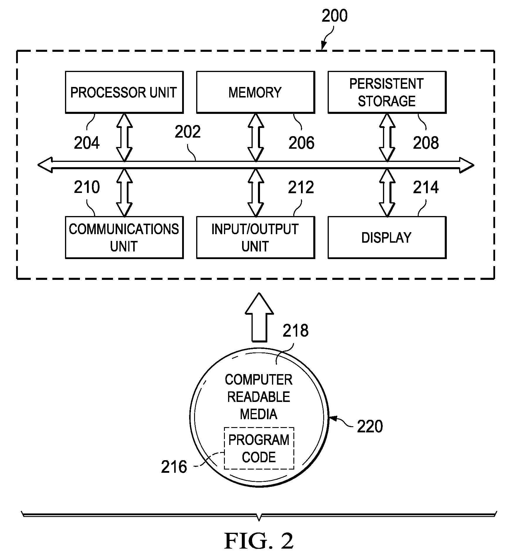
[0014]As will be appreciated by one skilled in the art, the present invention may be embodied as a system, method or computer program product. Accordingly, the present invention may take the form of an entirely hardware embodiment, an entirely software embodiment (including firmware, resident software, micro-code, etc.) or an embodiment combining software and hardware aspects that may all generally be referred to herein as a “circuit,”“module” or “system.” Furthermore, the present invention may take the form of a computer program product embodied in any tangible medium of expression having computer-usable program code embodied in the medium.

[0015]Any combination of one or more computer-usable or computer-readable medium(s) may be utilized. The computer-usable or computer-readable medium may be, for example but not limited to, an electronic, magnetic, optical, electromagnetic, infrared, or semiconductor system, apparatus, device, or propagation medium. More specific examples (a non-e...


PUM


Abstract

Illustrative embodiments provide a computer implemented method, a data processing system and a computer program product for synchronizing flows between transaction processing systems. In one illustrative embodiment, responsive to a failure or interruption in processing between systems, the computer implemented method locates all units of recovery for a particular connection to form a set of identified units of recovery and builds a single message containing the set of identified units of recovery. The computer implemented method further sends the single message from a sending system to a partner system for processing.

Description

BACKGROUND OF THE INVENTION[0001]1. Field of the Invention[0002]The present invention relates generally to an improved data processing system and more specifically to a computer implemented method, an apparatus and a computer program product for synchronizing flows between transaction processing systems.[0003]2. Description of the Related Art[0004]Transaction processing systems can collaborate together to support workloads distributed between the systems across a network connection. A global transaction executes in several different systems and any recoverable updates that the transaction performs can be coordinated using a two phase commit form of synchronization point management protocol. Failures of such systems or of the connections between them can result in work in progress being left in an incomplete state. Transactions left in an incomplete state then require resynchronization once communication between systems is re-established.[0005]In busy systems there can be large numbe...

Claims


Application Information

Patent Timeline
IPC IPC(8): G06F15/16
CPCG06Q10/06
Inventor BROOKS, MICHAEL DAVIDWRIGHT, ANDREW
Owner IBM CORP
Why Eureka
Try Eureka