
Water deviation unit for external wall fixtures

a technology for external wall fixtures and water deviation units, which is applied in the direction of snow traps, roof tools, building components, etc., can solve the problems of complex structure, serious danger, and bonshor's apparatus

Inactive Publication Date: 2009-12-31
VPL ENTERPRISES
View PDF3 Cites 2 Cited by
  • Summary
  • Abstract
  • Description
  • Claims
  • Application Information

AI Technical Summary

Benefits of technology

"The present invention provides a water deviation unit for external wall fixtures that overcomes the shortcomings of existing solutions. The unit has a simple structure, provides enhanced reliability and service life, and prevents damage to the composite wall. It includes a frame shaped plate and a box like subassembly projecting outwardly from the frame shaped plate. The subassembly includes a pair of spaced apart walls, an upper and lower horizontal plane, and upper and lower inclined planes. The subassembly also includes means for controlling an entrance and a withdrawal from an interior of a composite external wall. The technical effects of the invention include improved water management, prevention of damage to the composite wall, and enhanced reliability and service life of the water deviation unit."

Problems solved by technology

The use of features, adapted to be attached to external composite walls, creates, due to water infiltration from rain into the aforementioned walls, a serious danger.
The main disadvantage of Bonshor's apparatus resides in the use of two portions which slop downwardly from a center of the top of the protrusion towards the sides.
Another important disadvantage consists in dimensioning the transversal opening of the passageways in order to be suitable for different types of rain (from normal to torrential).
Yet another disadvantage of Bonshor's apparatus resides in its complicated structure: the passageways are formed by spaced-apart flanges and a connecting web.
First, the large, nailing, rectangular flange is attached only at its sides with nails which are predisposed to rust.
Second, the structure is complicated, a relatively large number of component being used.
Third, diverting the water to the sides does not seem practical and efficient.

Method used


Image

  • Water deviation unit for external wall fixtures
  • Water deviation unit for external wall fixtures
  • Water deviation unit for external wall fixtures

Examples


Embodiment Construction

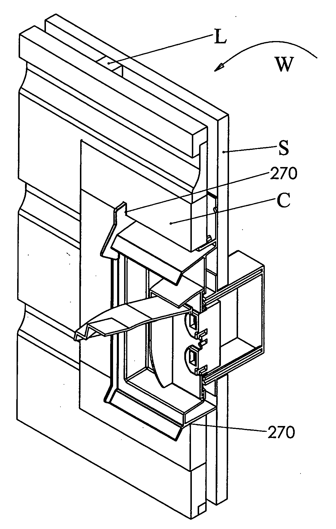
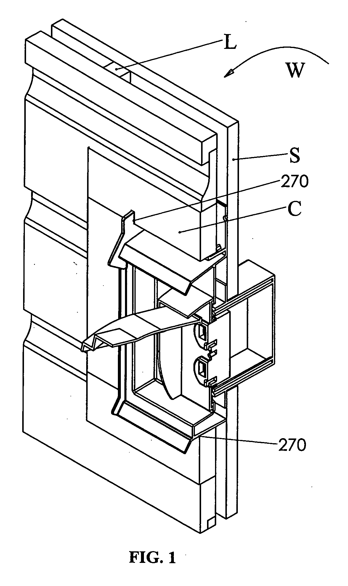
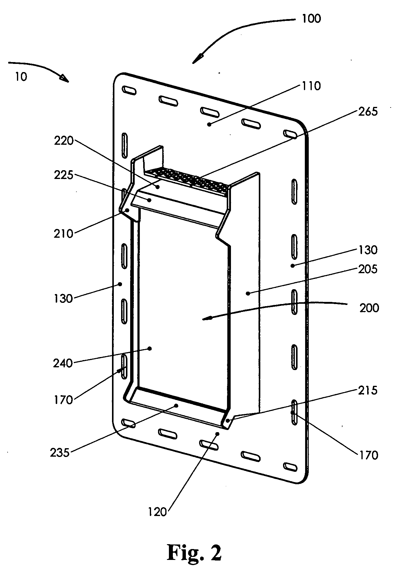
[0034]Referring to FIGS. 1-4, a water deviation unit for external wall fixtures is, generally, referenced as 10.

[0035]For convenience, in the following disclosure, it is to be agreed, that terms, such as “top”, “bottom”, “front”, “back”, “vertical”, “horizontal”, “upward”, “posterior” and “anterior”, “downward” and “outward” are conventionally employed with reference to the normal position in which unit 10 is used.

[0036]Water deviation unit for external wall fixtures 10 is mounted on a composite external wall that includes a sheathing S posteriorly situated and a cladding (siding) C anteriorly situated. Cladding C is usually made of stepped overlays of aluminum, vinyl, wood, etc. A plurality of laths L, interposed between sheathing S and cladding C, spaces apart and secures together the former and the later.

[0037]Broadly describing, with reference to FIGS. 1 through 4, water deviation unit for external wall fixtures 10 constitutes an integral structure including a frame shaped plate...


PUM


Abstract

A water deviation unit for external wall features comprises a frame shaped plate adaptable to be attached to a sheathing of a composite external wall and a box like subassembly projecting outwardly from and connecting to the frame shaped plate and provided centrally with a relatively large aperture. The box like subassembly includes: 1) a pair of spaced apart walls extending outwardly and perpendicularly in vertical planes from adjacent sides of said relatively large aperture and continuing above the latter; 2) upper and lower means for inclining used to deflect outwardly the water and connected laterally respectively at a top and a bottom of the pair of spaced apart walls; and 3) means for controlling an entrance and a withdrawal from an interior of the composite external, disposed between and joining the spaced apart walls.

Description

I. BACKGROUND OF THE INVENTION[0001]1. Field of the Invention[0002]The present invention relates to rain shielded mounting boxes used to pass through cladding of building walls and provide access from the outside to such features as gable, wall and soffit vents, electrical receptacles, light fixtures, dryer outlets, etc. The foregoing can be summarized by the above title.[0003]2. Description of the Prior Art[0004]The use of features, adapted to be attached to external composite walls, creates, due to water infiltration from rain into the aforementioned walls, a serious danger. Attempts have been made to eliminate or at least to alleviate this danger. Thus, U.S. Pat. No. 6,951,081, granted on Oct. 4, 2005 to Bonshor for a “WATER DEFLECTING APPARATUS” and U.S. Pat. No. 7,358,440, granted on Apr. 15, 2008 to Funk et al. for a “RAIN SHIELDED BOX FOR EXITING THROUGH SIDING” have addressed the problem.[0005]Bonshor's patent discloses an apparatus mounted on a wall which includes a sheathi...

Claims


Application Information

Patent Timeline
Patent Type & Authority Applications(United States)
IPC IPC(8): E04B1/70H02G3/08
CPCH02G3/088
Inventor CHAN, JAMES CHUN NAMREBEL, JACOB
Owner VPL ENTERPRISES
Learn More