Coupling Assembly

a technology of coupling assembly and coupling tube, which is applied in the direction of couplings, pipe couplings, mechanical equipment, etc., can solve the problems of electrical sparks and fuel ignition in lines caused by electrostatic charges

Active Publication Date: 2009-12-31
EATON INTELLIGENT POWER LIMITED
View PDF14 Cites 28 Cited by
  • Summary
  • Abstract
  • Description
  • Claims
  • Application Information

AI Technical Summary

Benefits of technology

[0008]In another embodiment, a coupling assembly for releasably interconnecting a fluid joint is provided, where the fluid joint includes confronting ends of a pair of fluid conveying members, each of which has a ferrule fixedly attached thereto, and a sleeve circumferentially surrounding the ferrules. The coupling assembly includes a pair of coupling members, each of which has a first end and a second end, a hinge assembly configured to hingedly connect the first ends of the coupling members to permit them to rotate relative to each other between an open position and a closed position where the coupling members surround the sleeve, a pair of bonding wires, each of wh

Problems solved by technology

A stored electrostatic charge may give rise to the hazard of an electrical spark in the presence of vaporized fuel.
Discharge of the spark by grounding or by flexing of the coupling in such a manner to b

Method used


Image

  • Coupling Assembly
  • Coupling Assembly
  • Coupling Assembly

Examples


Embodiment Construction

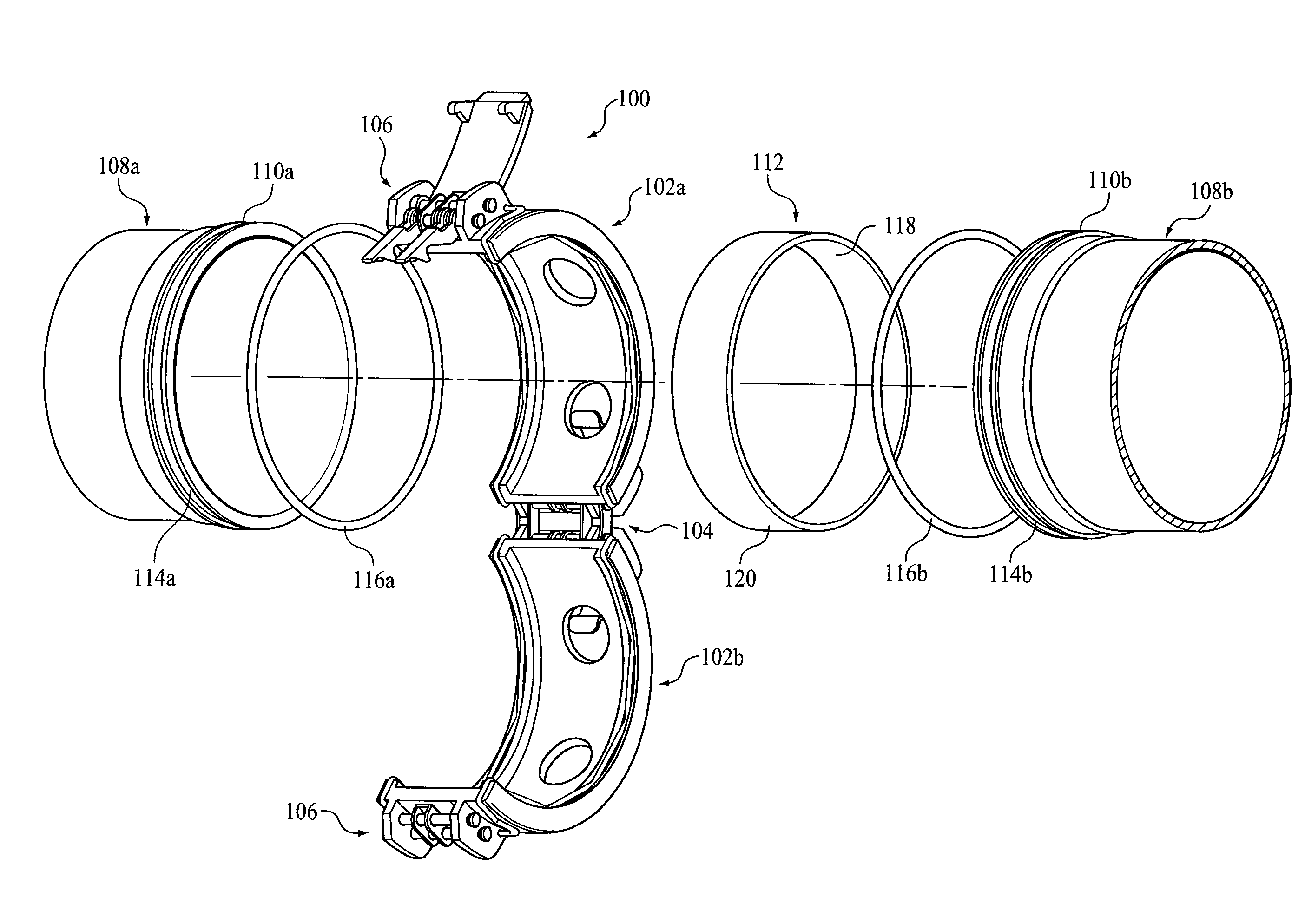
[0021]Certain terminology will be used in the foregoing description for convenience in reference only and will not be limiting. The terms “forward” and “rearward” with respect to each component of the coupling assembly will refer to direction towards and away from, respectively, the coupling direction. The terms “rightward” and “leftward” will refer to directions in the drawings in connection with which the terminology is used. The terms “inwardly” and “outwardly” will refer to directions toward and away from, respectively, the geometric centerline of the coupling assembly. The terms “upward” and “downward” will refer to directions as taken in the drawings in connection with which the terminology is used. All foregoing terms mentioned above include the normal derivative and equivalents thereof.

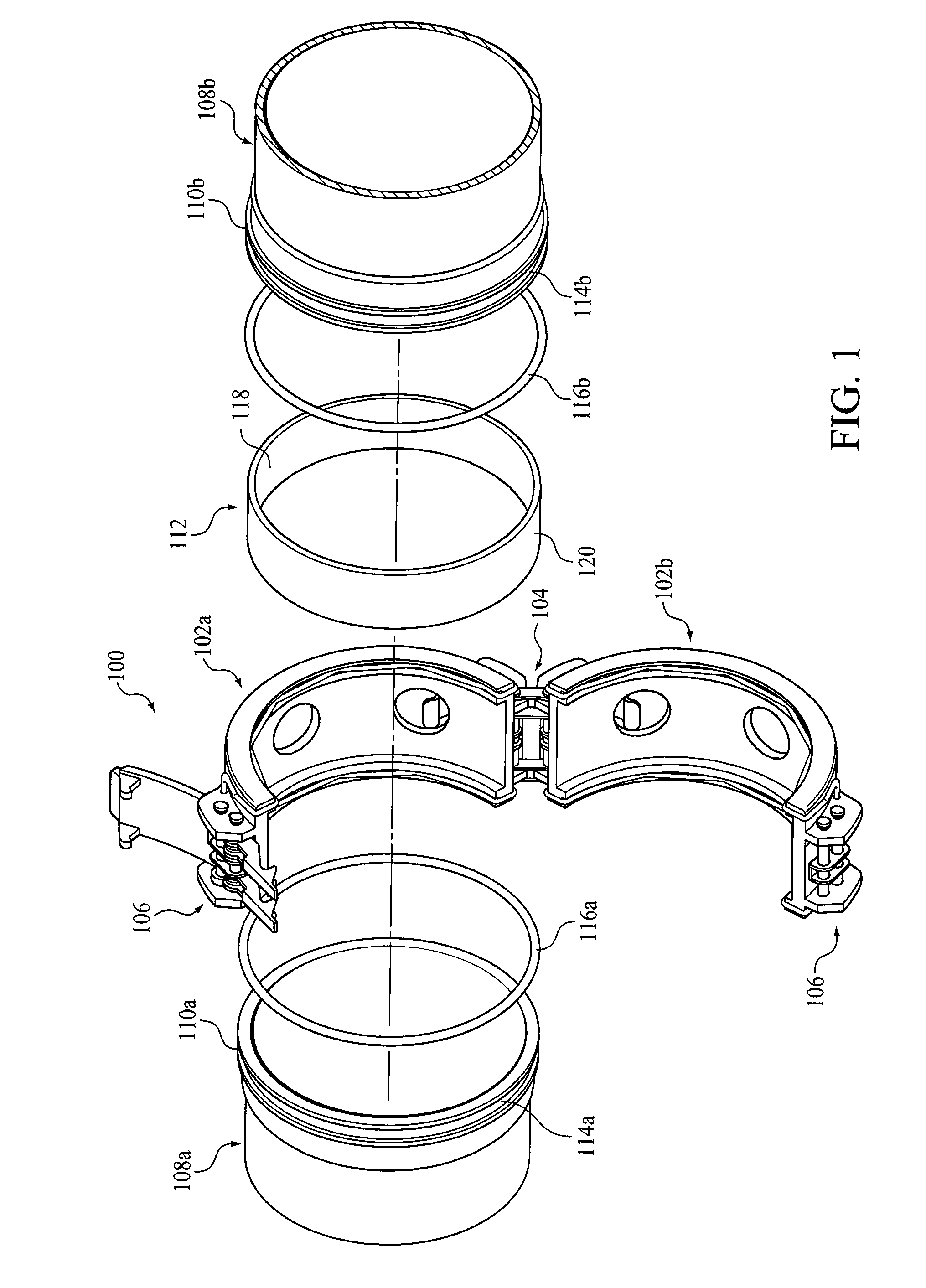
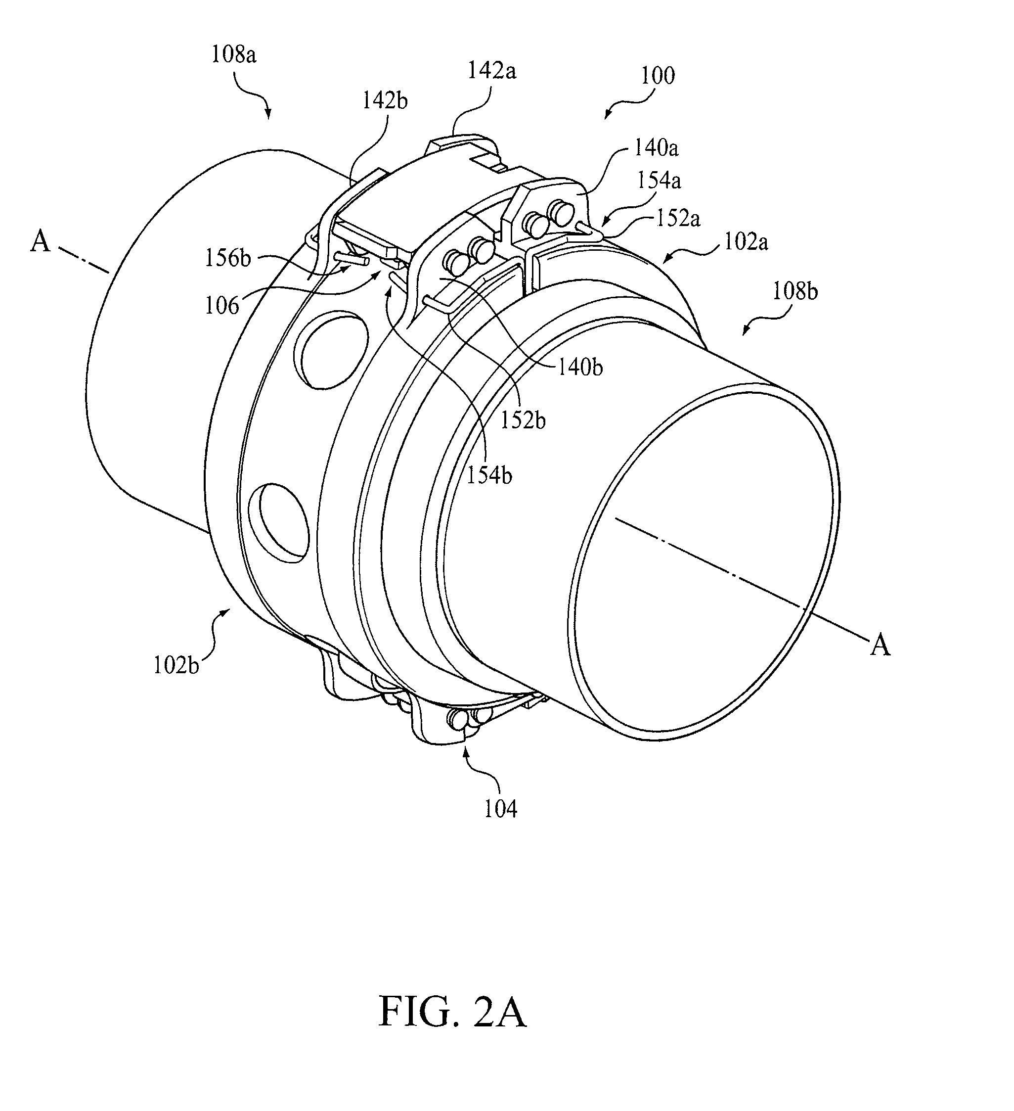
[0022]With reference to FIGS. 1-5B, one embodiment of a coupling assembly 100 for use in a fluid conveying application, such as a low pressure aircraft fuel system, is described. The coupling ...


PUM


Abstract

A coupling assembly for releasably interconnecting a fluid joint is provided where the fluid joint includes confronting ends of a pair of fluid conveying members, each of which has a ferrule fixedly attached thereto, and a sleeve circumferentially surrounding the ferrules. The coupling assembly includes a pair of coupling members, each of which has a first end and a second end, a hinge assembly configured to hingedly connect the first ends of the coupling members to permit them to rotate relative to each other between an open position and a closed position where the coupling members surround the sleeve, a pair of bonding wires, each of which is coupled to a respective coupling member and configured to electrically bond the respective coupling member to the ferrules of respective fluid conveying members, and a releasable latching assembly configured to releasably secure the second ends of the coupling members together when they are in their closed position. Optionally, the coupling assembly includes a pair of bonding members, each of which is externally mounted to a respective coupling member and configured to electrically bond the respective coupling member to the sleeve and/or a latch indicator configured to be moved to a closed position over the releasable latching assembly only when the second ends of the coupling members are secured together by the releasable latching assembly.

Description

BACKGROUND [0001]1. Field of the Invention[0002]The present application relates to coupling assemblies for interconnecting confronting ends of a pair of fluid conveying members, and more particularly, to a clamshell variety coupling assembly for interconnecting confronting ends of a pair of fluid conveying members.[0003]2. Description of the Related Art[0004]There are a number of prior art couplings that are used for interconnecting various types of fluid conveying lines or conduits. Depending upon the type of fluid to be conveyed, the prior art couplings may be designed to handle special safety requirements. Particularly for conduits which convey fuel, there is always a concern for designing a coupling so that an electrostatic charge does not build up on one of the coupled sections of the line. A stored electrostatic charge may give rise to the hazard of an electrical spark in the presence of vaporized fuel. Discharge of the spark by grounding or by flexing of the coupling in such ...

Claims


Application Information

Patent Timeline
IPC IPC(8): F16L23/18
CPCF16L23/04F16L2201/10F16L25/01F16L23/06
Inventor WERN, DAVID E.BREAY, CLIFTON P.STATLER, III, RICHARD L.
Owner EATON INTELLIGENT POWER LIMITED
Why Eureka
Try Eureka