Communication terminal and communication switching method
Active Publication Date: 2009-12-31
PANASONIC INTELLECTUAL PROPERTY CORP OF AMERICA
View PDF6 Cites 70 Cited by
Summary
Abstract
Description
Claims
Application Information
AI Technical Summary
This helps you quickly interpret patents by identifying the three key elements:
Problems solved by technology
Method used
Benefits of technology
Benefits of technology
[0011]In this way, when the second terminal to which switching is directed is waiting for a response to a switch connection request transmitted from it and receives a switch connection request from the first communication terminal, the second terminal to which switching is directed detects that switching processes are being performed simultaneously in both the first communication terminal and the second communication terminal. At this time, the second terminal to which switching is directed stops a switching session related to one switch connection request, and continues a switching session related to the other switch connection request. At this time, the switching sessions can be combined by including information on the switching process to be stopped in the switching session to be continued, and switching on both ends can be carried out simultaneously. This eliminates the requirement for starting reprocessing by a user or application, or for restarting a switching process which is a procedure to control multimedia communication, and allows both communication terminals performing multimedia communication with each other to be switched simultaneously and quickly.
[0042]Since a collision of switching processes is solved in signaling procedures, a user or an application is not required to perform reprocessing, the burden is reduced, and multimedia communication can be switched quickly and simultaneously.
Problems solved by technology
However, since there are limitations on the terminal capability and transmission capability of a portable communication terminal, there are limits to the functionality in multimedia communication, such as the screen size and the frame rate.
Method used
Image
Click on the blue label to locate the original text in one second.
Reading with bidirectional positioning of images and text.
Examples
first embodiment
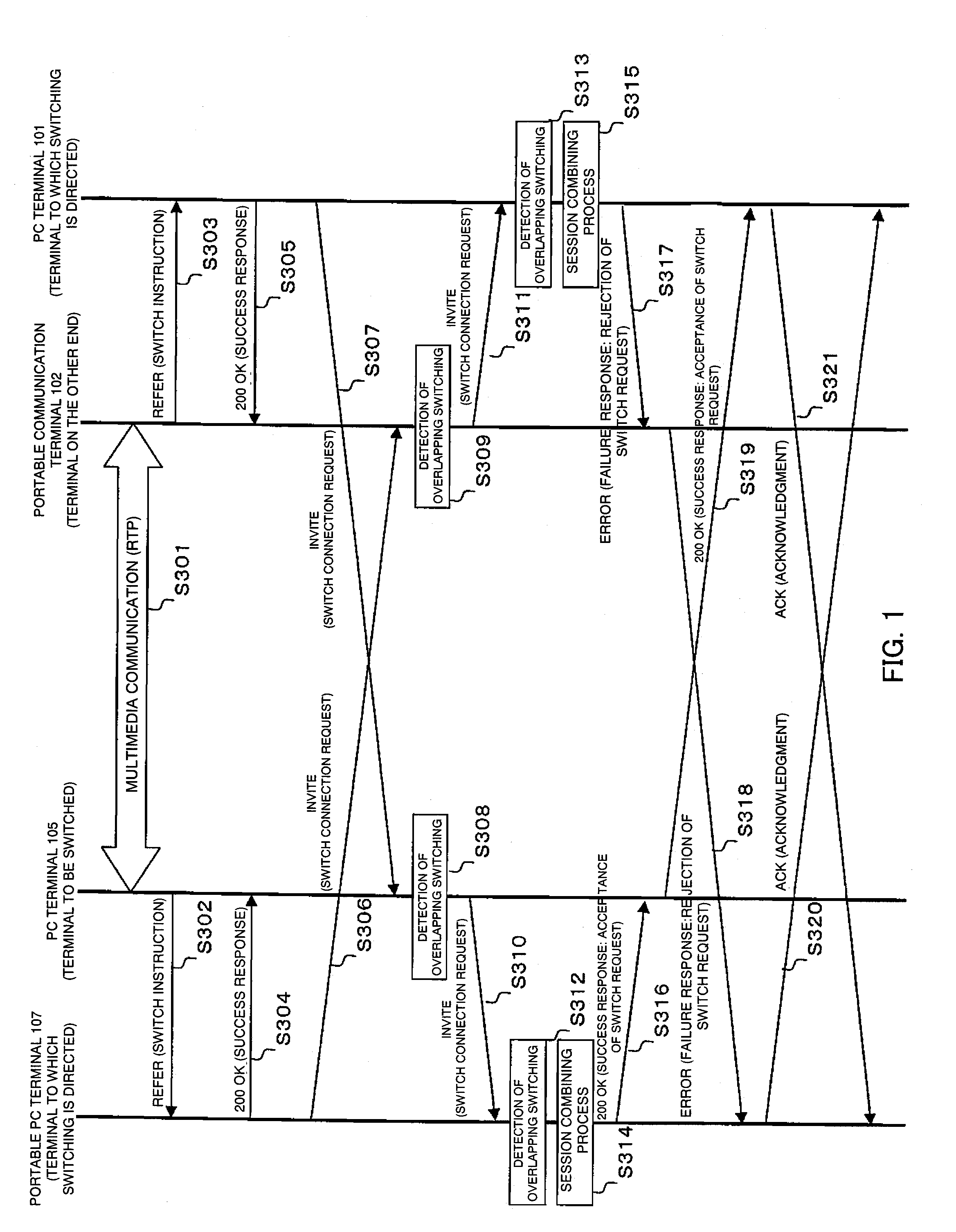
[0080]FIG. 1 shows an operation of a communication switching method of an embodiment of the invention. Before the communication switching method will be described, a network system and a communication terminal that realizes the communication switching method will be described with reference to FIGS. 2 and 3.
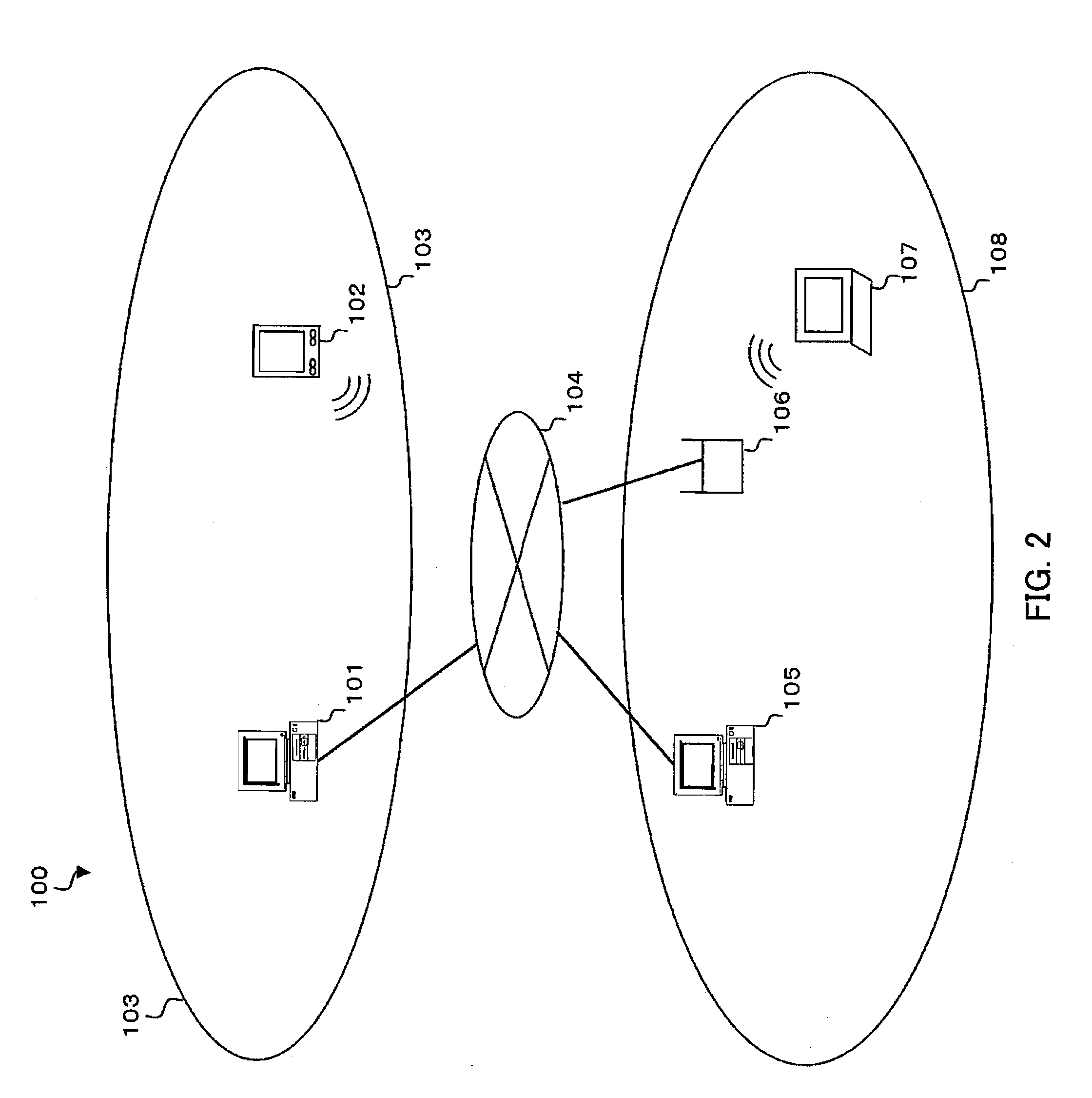
[0081]FIG. 2 shows a configuration of a network system 100 of the embodiment. The network system 100 of the embodiment has an IP network 104, local IP networks 103 and 108 connected to the IP network 104, and various kinds of communication terminals connected to the local IP networks 103 and 108. The various kinds of communication terminals include PC terminals 101 and 105, a portable communication terminal 102, an access point 106, and a portable PC terminal 107. The portable PC terminal 107 is connected via the access point 106 to the local IP network 108.
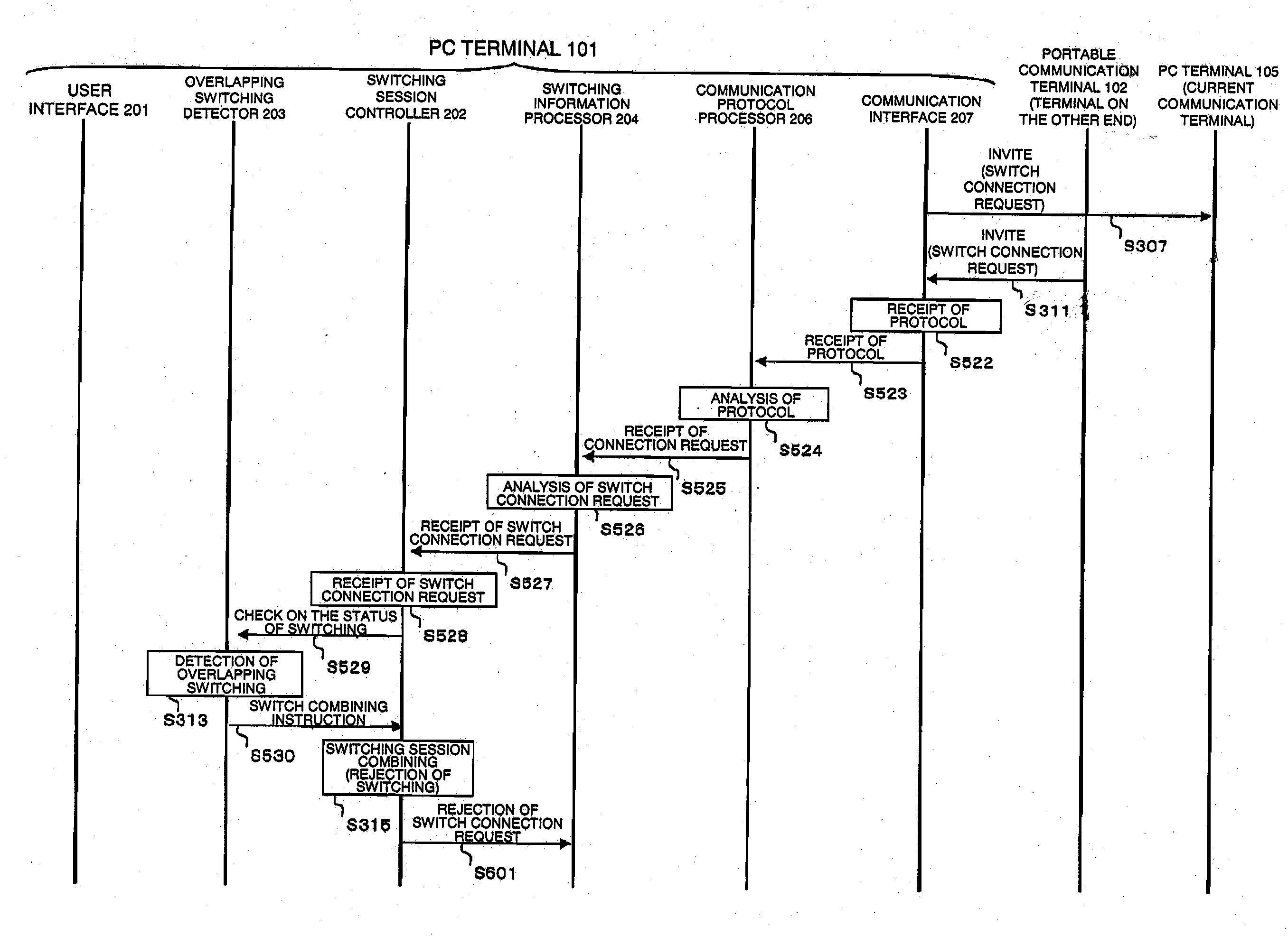
[0082]FIG. 3 is a block diagram showing a configuration of a terminal, such as the PC terminals 101 and 105, the portable co...
second embodiment
[0147]FIGS. 25 and 26 illustrate a communication method in the network system 100 of a second embodiment of the invention. An operation of the embodiment is basically the same as the communication method of the first embodiment, but is different in switching procedures in a communication protocol. Points in which the second embodiment differs from the first embodiment will be described in the following.
[0148]In FIG. 25, procedures up to a procedure in which each of the PC terminal 105 and the portable communication terminal 102, which are end communication terminals between which multimedia communication is established, detects an overlapping switching (S301 to S309) are the same as the procedures S301 to S309 in FIG. 1. An overlapping switching is detected by an identifier of a session to be switched indicated in a Replaces header in a switch connection request. Then, in the embodiment, the PC terminal 105 and the portable communication terminal 102 both transmit failure responses ...
third embodiment
[0152]FIGS. 27 and 28 illustrate a communication method in the network system 100 of a third embodiment of the invention. An operation of the embodiment is basically the same as the communication methods of the first and second embodiments, but is different in switching procedures in a communication protocol. Points in which the third embodiment differs from the above-described embodiments will be described in the following.
[0153]In FIG. 27, when the PC terminal 105 and the portable communication terminal 102, which are end communication terminals 200 between which multimedia communication is established, perform switching processes, they transmit switch instructions to the terminals on the other ends of communication (S1301 and S1302). In this case, identifiers of the current sessions indicated in Call-ID headers in the switch instructions are the same, and therefore they both detect overlapping switching processes (S1303 and S1304). As a session combining process, an end communica...
PUM
Abstract
A switch instruction is transmitted from a PC terminal (105) to a portable PC terminal (107) (S302); the portable PC terminal (107) transmits a switch connection request to a portable communication terminal (102) on the other end of communication (S306); the portable PC terminal (107), when it is waiting for a response to the switch connection request and receives a switch connection request from the other end of communication, detects that switching processes are being performed simultaneously (S312); upon detection of the simultaneous switching, a switching session related to either switch connection request is determined to be continued (S314 and S315); the portable PC terminal (107), which received the switch connection request to which the switching session determined to be continued was related, transmits a success response including information on the switching process of the portable PC terminal (107) side (S316 and S319); and the PC terminal 101, which received the switch connection request to which the one to be stopped was related, transmits a failure response (S317 and S318). This allows switching to be carried out with quick and not many procedures in both end communication terminals performing multimedia communication with each other.
Description
REFERENCE TO RELATED APPLICATIONS[0001]This application claims the benefit of Japanese Patent Application No. 2005-176064 filed on Jun. 15, 2005 in Japan, the contents of which are incorporated herein by reference.TECHNICAL FIELD[0002]This invention relates to a communication terminal to be connected to a network, and to a communication switching method using the communication terminal.BACKGROUND ART[0003]Portable communication terminals such as portable telephones and PDAs have become widespread recently, and they are changing so that they can be used for videophones, receiving content delivery services, or other multimedia communication. However, since there are limitations on the terminal capability and transmission capability of a portable communication terminal, there are limits to the functionality in multimedia communication, such as the screen size and the frame rate. When there is, around a user, a multimedia terminal that can perform more functional multimedia communicatio...
Claims
Application Information
Patent Timeline
Application Date:The date an application was filed.
Publication Date:The date a patent or application was officially published.
First Publication Date:The earliest publication date of a patent with the same application number.
Issue Date:Publication date of the patent grant document.
PCT Entry Date:The Entry date of PCT National Phase.
Estimated Expiry Date:The statutory expiry date of a patent right according to the Patent Law, and it is the longest term of protection that the patent right can achieve without the termination of the patent right due to other reasons(Term extension factor has been taken into account ).
Invalid Date:Actual expiry date is based on effective date or publication date of legal transaction data of invalid patent.

