Optical Disk Labeling Device

a labeling device and optical disk technology, applied in auxillary welding devices, soldering equipment, paper/cardboard containers, etc., can solve the problems of optical disk damage, optical disk unbalance, difficult to recognize from outside appearance, etc., and achieve the effect of simplifying the structure and reducing elements

Inactive Publication Date: 2010-01-07
HONG SHU CHI
View PDF4 Cites 0 Cited by
  • Summary
  • Abstract
  • Description
  • Claims
  • Application Information

AI Technical Summary

Benefits of technology

[0006]The primary object of the present invention is to solve the aforesaid disadvantages by reducing elements and simplifying the structure of an optical disk labeling device.

Problems solved by technology

Whether an optical disk has data stored thereon is difficult to recognize from outside appearance.
However, the oil-based ink of the mark pen tends to damage the optical disk, and adding the label makes the weight of the optical disk unbalanced and could result in damage of the optical disk drive during high speed rotation.
While the techniques and devices mentioned above can bond a label onto an optical disk, they consist of a great deal of components and cause higher production costs.
Fabrication and assembly are more complex.

Method used


Image

  • Optical Disk Labeling Device
  • Optical Disk Labeling Device
  • Optical Disk Labeling Device

Examples


Embodiment Construction

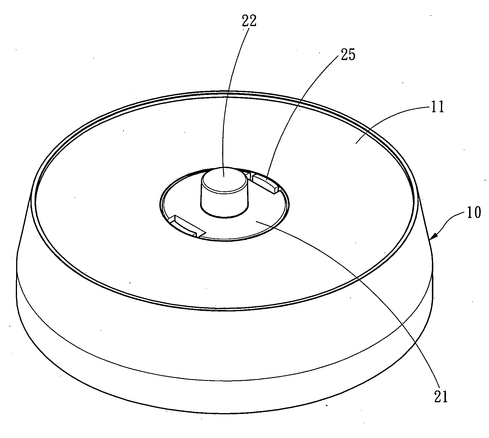
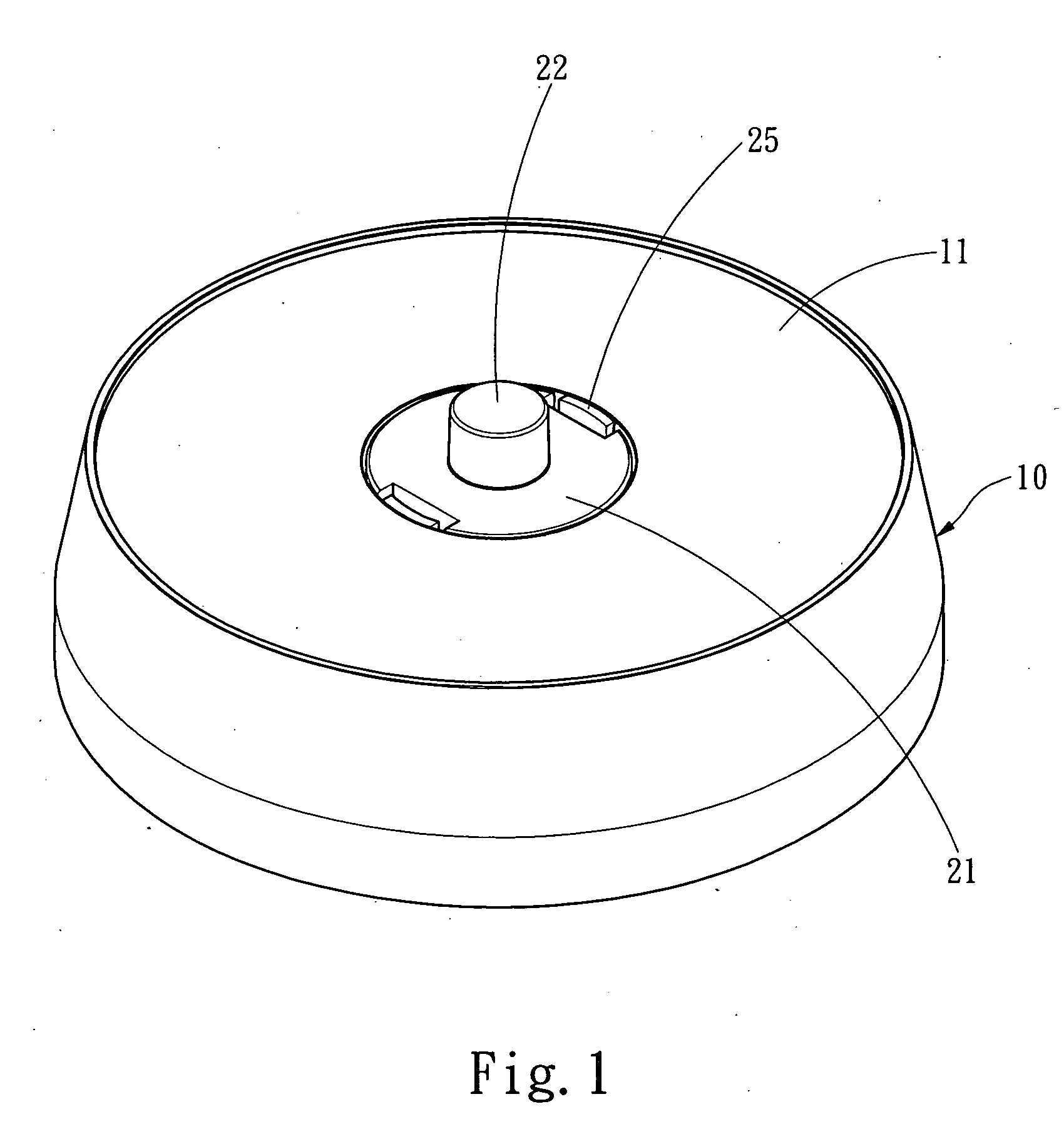
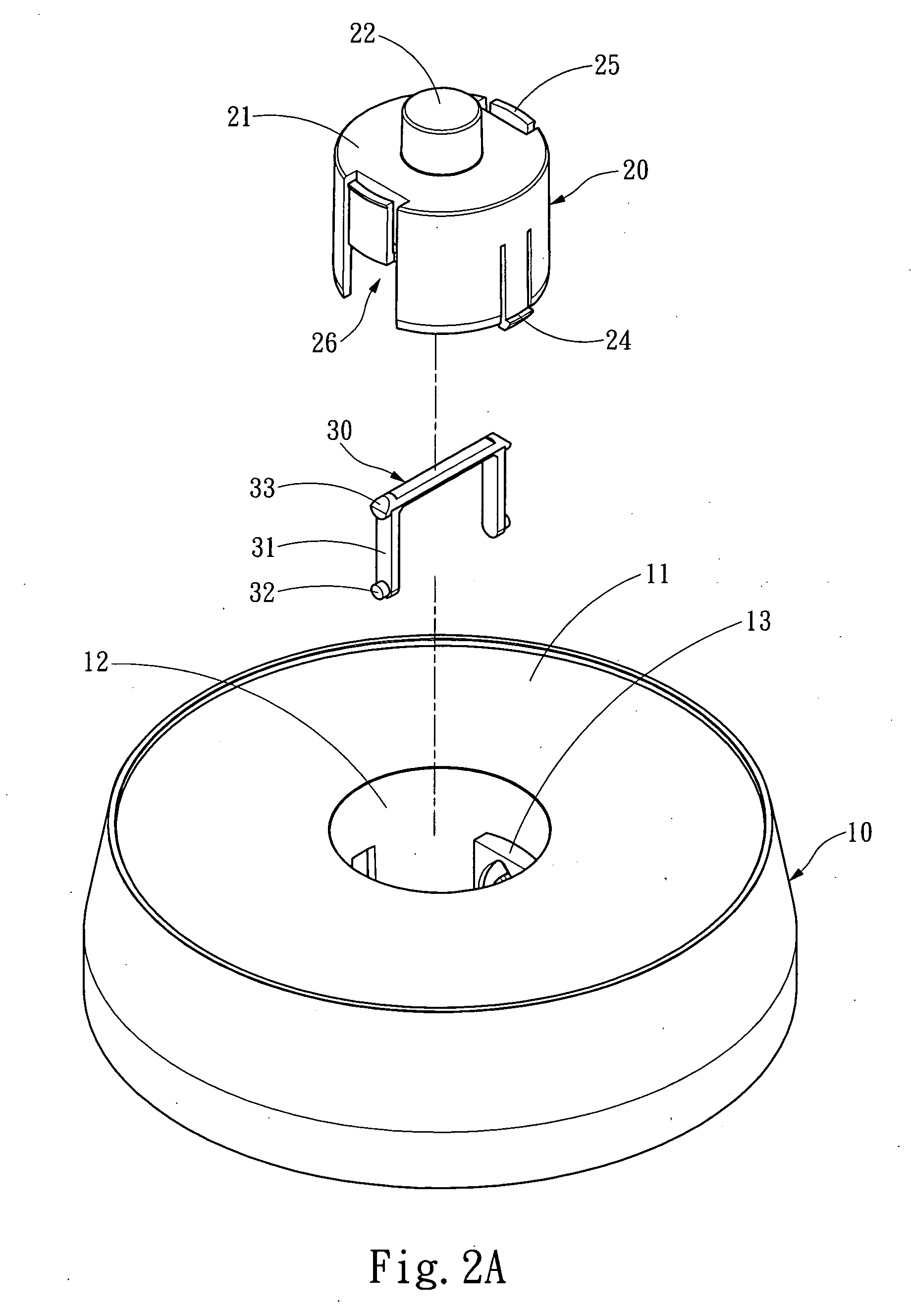
[0015]Please referring to FIGS. 1 through 4B, the optical disk labeling device according to the invention includes a label holding dock 10 and an optical disk holding dock 20. The label holding dock 10 has a label holding surface 11 and a plurality of bracing struts 15 at the bottom to support the label holding surface 11, and a holding portion 12 with an opening formed on the label holding surface 11. The holding portion 12 has two track portions 13, and each track portion 13 has a downward track 130 and an upward track 131 that have two ends communicate with each other to form a first anchor portion 132 and a second anchor portion 133. The downward track 130 is formed at a depth gradually decreasing from the first anchor portion 132 to the second anchor portion 133. The downward track 130 also has a release section 134 at the second anchor portion 133. The release section 134 is formed at a depth greater than the depth of the downward track 130 and close to the depth of the second...


PUM

PropertyMeasurementUnit
depressing forceaaaaaaaaaa
depthaaaaaaaaaa
perimeteraaaaaaaaaa

Abstract

An optical disk labeling device aims to improve the disadvantages of conventional optical disk labeling devices that have too many elements, which causes higher production cost and complicated fabrication and assembly processes. It includes a label holding dock containing a holding portion and an optical disk holding dock slidably located on the holding portion. The holding portion has a downward track and an upward track. The downward track and the upward track have two ends forming a first anchor portion and a second anchor portion that communicate with each other. Through an actuation member the optical disk holding dock can be anchored on the first anchor portion at a first position to receive a first depressing force so that the actuation member is moved along the downward track to the second anchor portion to hold the optical disk holding dock at a second position. At the second position the optical disk holding dock can receive a second depressing force so that the actuation member slides along the upward track until reaching the first anchor portion and allows the optical disk holding dock to return to the first position. Thus the number of total elements required is fewer and production cost is lower.

Description

FIELD OF THE INVENTION[0001]The present invention relates to an optical disk labeling device and particularly to an optical disk labeling device to bond a label on an optical disk.BACKGROUND OF THE INVENTION[0002]Optical disk is a storage medium to store digital data. As optical disk burners become increasingly popular the chance of using the optical disk to store data also is greater. Whether an optical disk has data stored thereon is difficult to recognize from outside appearance. Hence users generally make marks on the optical disk for recognition. A common approach is making a mark through a mark pen or by bonding a label. However, the oil-based ink of the mark pen tends to damage the optical disk, and adding the label makes the weight of the optical disk unbalanced and could result in damage of the optical disk drive during high speed rotation.[0003]At present most optical disks are labeled by optical disk labeling devices. U.S. Pat. No. 5,783,033 discloses a labeling device wh...

Claims


Application Information

Patent Timeline
Patent Type & Authority Applications(United States)
IPC IPC(8): B32B37/00
CPCB65C9/265Y10T156/1309Y10T156/17Y10T156/10Y10T156/1744Y10T156/18
Inventor HONG, SHU-CHI
Owner HONG SHU CHI
Why Eureka
Try Eureka