Terminal portion structure of optical transmission element

a technology of optical transmission element and terminal portion, which is applied in the direction of optics, instruments, optical light guides, etc., can solve the problems of difficult assembly, difficult assembly, and difficult assembly of the above-mentioned optoelectronic components, and achieves the effect of broadening the application of the terminal portion structure, increasing the tolerance of the inclination angle, and increasing the tolerance of the distan

Inactive Publication Date: 2022-04-14
CLOUD LIGHT TECH LTD
View PDF0 Cites 0 Cited by
  • Summary
  • Abstract
  • Description
  • Claims
  • Application Information

AI Technical Summary

Benefits of technology

[0021]According to the present disclosure, the terminal portion structure of an optical transmission element increases the tolerance of the distance between the laser emission element or light signal receiving element and the light guiding component, increases the tolerance of the inclination angle of the cross section of the terminal portion of the light guiding component, broadens the application of the terminal portion structure of an optical transmission element to various laser emission elements or light signal receiving elements, renders assembly and manufacturing easy, and downsizes related elements.

Problems solved by technology

However, both the laser emission element and light signal receiving element hardly permit the tolerance of the distance between an optical fiber (or a planar lightwave circuit) and another optical fiber (or another planar lightwave circuit), leading to difficulties in assembly.
For instance, the laser emission element and / or light signal receiving element must be spaced apart from the optical transmission element by a distance of 20 to 40 μm; thus, during the process of aligning two components, the tips of the optical fibers or the surfaces of the aforesaid optoelectronic components are likely to be damaged.
However, the aforesaid conventional technique requires precise control of the grinding of the optical transmission elements.
Therefore, the prior art is still unable to eradicate the difficulties in manufacturing and assembly.

Method used


Image

  • Terminal portion structure of optical transmission element
  • Terminal portion structure of optical transmission element
  • Terminal portion structure of optical transmission element

Examples


first embodiment

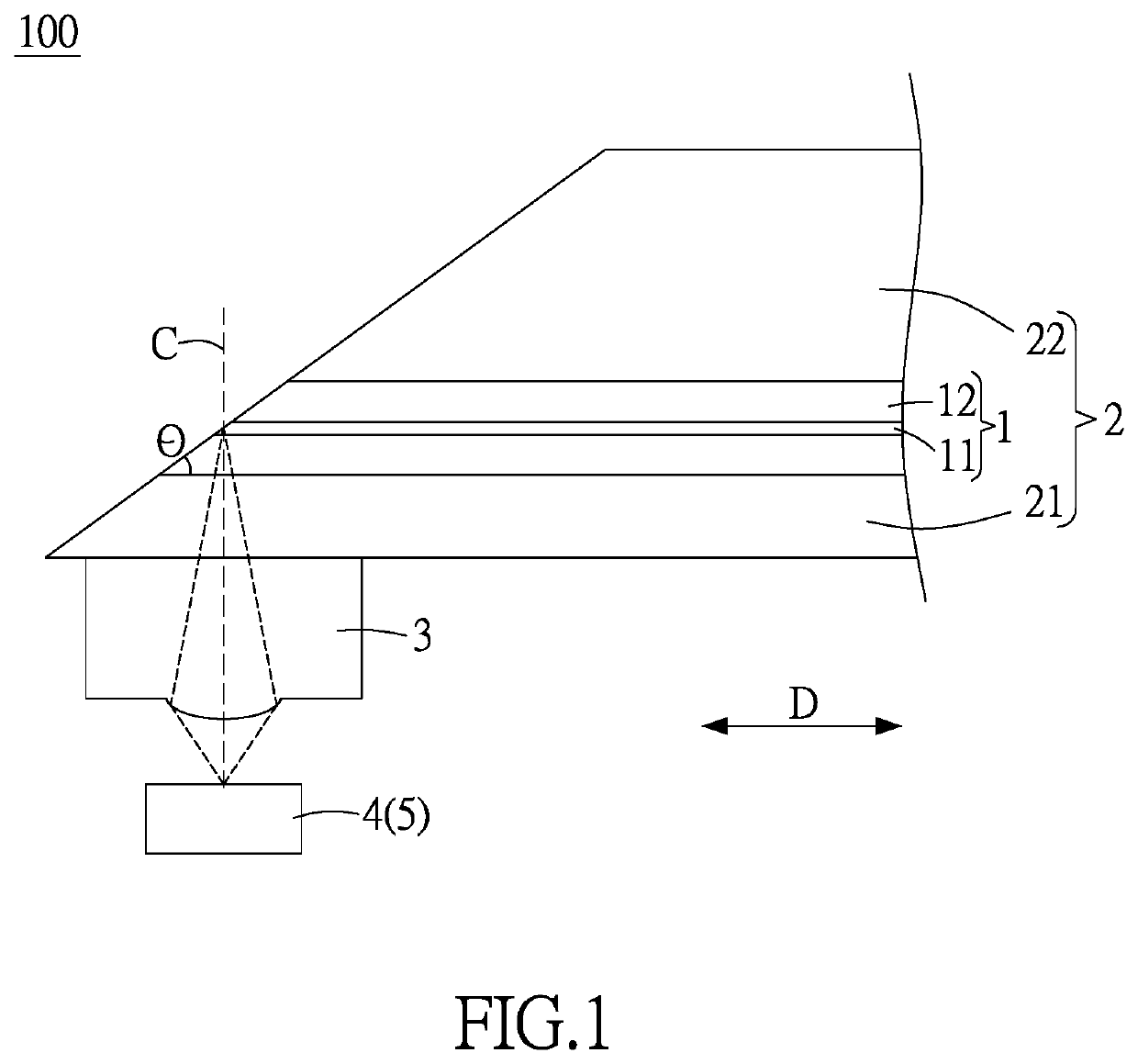
[0030]As shown in FIG. 1, in the present disclosure, a terminal portion structure 100 of an optical transmission element comprises a light guiding component 1, a glass protection layer 2 and a convex lens 3.

[0031]The light guiding component 1 comprises a core 11 and a cladding 12 enclosing the core 11. The refractive index of the cladding 12 is less than the refractive index of the core 11, allowing light signals to be transmitted in the light guiding component 1 by total internal reflection.

[0032]The glass protection layer 2 covers at least the terminal portion of the light guiding component 1. According to the present disclosure, the glass protection layer 2 includes a lower lid 21 and an upper lid 22. The lower lid 21 and the upper lid 22 are coupled together to fully enclose the light guiding component 1. In this embodiment, the difference between the “upper” part and the “lower” part is defined by the direction in which the terminal portion structure 100 of an optical transmiss...

second embodiment

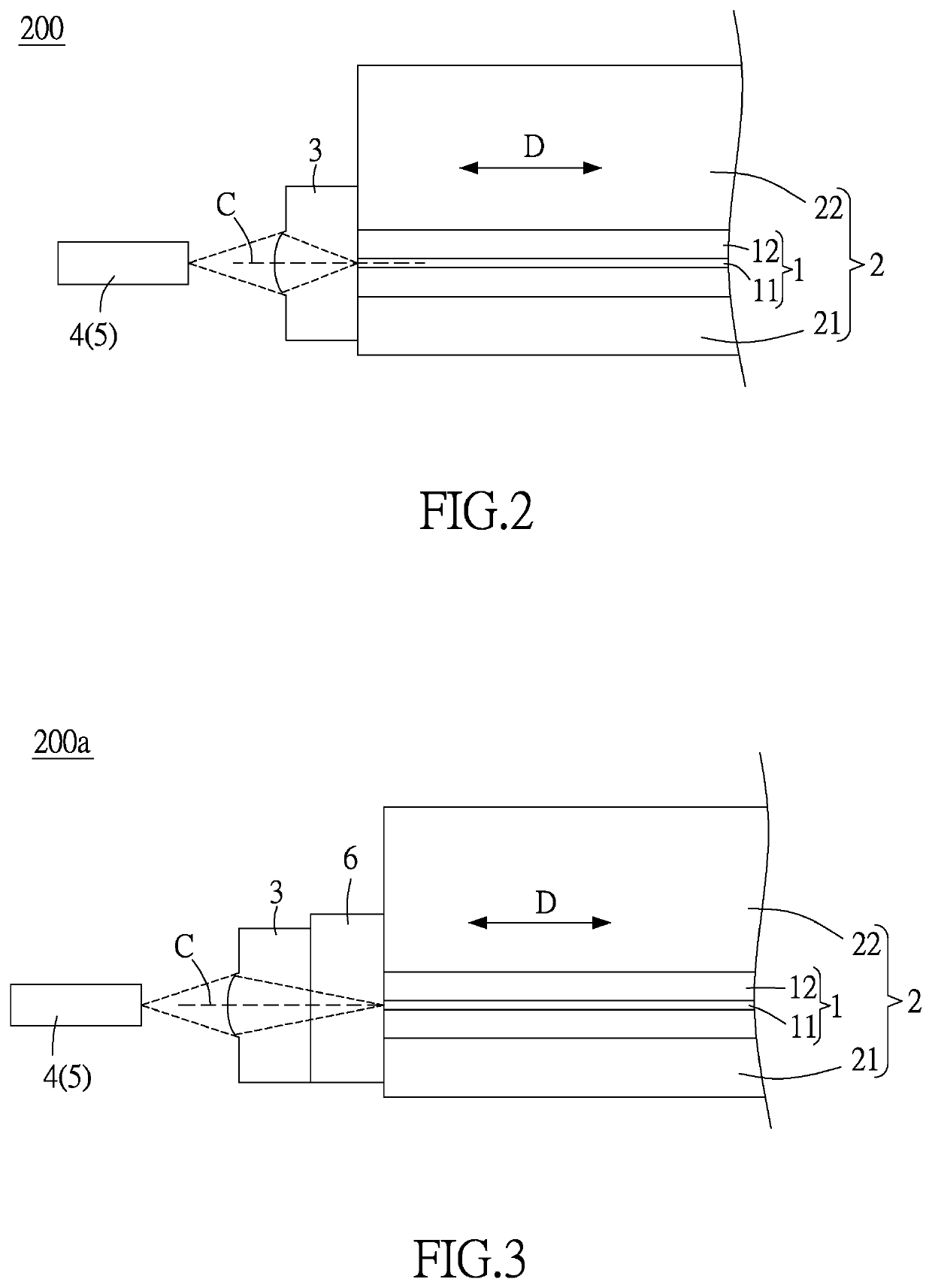
[0043]The present disclosure further provides the As shown in FIG. 2, a terminal portion structure 200 of an optical transmission element comprises a light guiding components 1, a glass protection layer 2 and a convex lens 3.

[0044]The light guiding components 1 comprises a core 11 and a cladding 12 enclosing the core 11. The refractive index of the cladding 12 is less than the refractive index of the core 11, allowing light signals to be transmitted in the light guiding components 1 by total internal reflection.

[0045]The glass protection layer 2 covers at least the terminal portion of the light guiding component 1. According to the present disclosure, the glass protection layer 2 is divided into a lower lid 21 and an upper lid 22. The lower lid 21 and the upper lid 22 are coupled together to fully enclose the light guiding component 1. However, the present disclosure is not limited thereto, the glass protection layer 2 may be integrally formed to enclose the light guiding component...

third embodiment

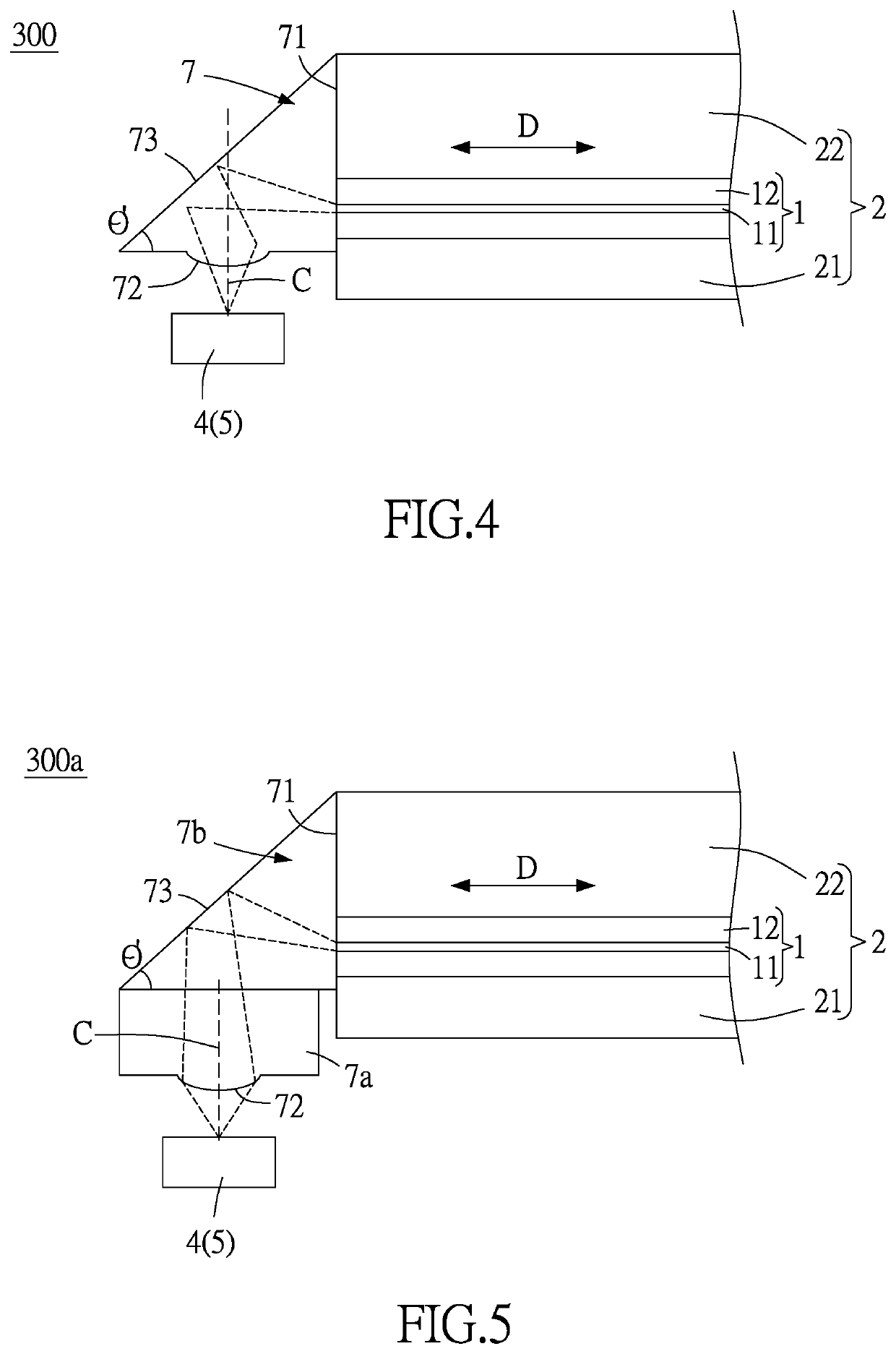
[0053]The present disclosure further provides the As shown in FIG. 4, a terminal portion structure 300 of an optical transmission element comprises a light guiding component 1, a glass protection layer 2 and a prismatic convex lens 7.

[0054]The light guiding component 1 comprises a core 11 and a cladding 12 enclosing the core 11. The refractive index of the cladding 12 is less than the refractive index of the core 11, allowing light signals to be transmitted in the light guiding components 1 by total internal reflection.

[0055]The glass protection layer 2 covers at least the terminal portion of the light guiding component 1. According to the present disclosure, the glass protection layer 2 is divided into a lower lid 21 and an upper lid 22. The lower lid 21 and the upper lid 22 are coupled together to fully enclose the light guiding component 1. However, the present disclosure is not limited thereto, as the glass protection layer 2 may be integrally formed to enclose the light guidin...


PUM

PropertyMeasurementUnit
included angleaaaaaaaaaa
distanceaaaaaaaaaa
angleaaaaaaaaaa

Abstract

A terminal portion structure of an optical transmission element includes a light guiding component, glass protection layer and convex lens. The light guiding component includes a core and a cladding enclosing the core. The cladding is of a lower refractive index than the core, allowing light signals to be transmitted in the light guiding component by total internal reflection. The glass protection layer covers at least a terminal portion of the light guiding component. The convex lens is disposed on one side of the glass protection layer. The cross section of the terminal portion of the light guiding component tilts relative to the axial direction of the light guiding component. The optical axis of the convex lens is perpendicular to the axial direction of the light guiding component. The focal point of the convex lens is located at the cross section of the terminal portion of the core.

Description

CROSS-REFERENCE TO RELATED APPLICATION[0001]This non-provisional application claims priority under 35 U.S.C. § 119(a) on Patent application No(s).109135064 filed in Taiwan, R.O.C. on Oct. 8, 2020, the entire contents of which are hereby incorporated by reference.BACKGROUND OF THE INVENTION1. Field of the Invention[0002]The present disclosure relates to optical transmission elements, and in particular to a terminal portion structure of an optical transmission element.2. Description of the Related Art[0003]Optical fibers are fibers made of glass or plastic. Light travels in optical fibers by total internal reflection. By contrast, planar lightwave circuits are made of glass and silicon by a semiconductor manufacturing process (including deposition and etching). Light also travels in planar lightwave circuits by total internal reflection. Optical fibers and planar lightwave circuits, also known as optical transmission elements, have better modulation rate and longer transmission distan...

Claims


Application Information

Patent Timeline
Patent Type & Authority Applications(United States)
IPC IPC(8): G02B6/42
CPCG02B6/4206G02B6/4214G02B6/4243
Inventor LIN, EN-HUNGTIEN, CHANG-HUNGMA, BO-HONGTSAI, JUI-TING
Owner CLOUD LIGHT TECH LTD
Why Eureka
Try Eureka