Corner canvas and corner awning device

a corner awning and canvas technology, applied in the field of corner awning devices, can solve the problems of impairment of the ornamental and exterior appearance of the corner spaces of the perimeter of the building, and achieve the effect of enhancing ornamentality and external appearan

Inactive Publication Date: 2010-01-07
ITO OSAMU
View PDF21 Cites 2 Cited by
  • Summary
  • Abstract
  • Description
  • Claims
  • Application Information

AI Technical Summary

Benefits of technology

[0060]Thereby, corner spaces of the perimeters of various buildings can be covered effectively, while the awning devices can be stored compactly by the wall of a corner when stored.
[0061]As a result, an epoch-making novel product is provided to the industry, which dramatically enhances ornamentality and external appearances in the corners of various buildings and which abounds in technical interests and utility as a corner awning device.

Problems solved by technology

However, using such a cheap technique, the decorativeness and appearance of the corner spaces of the perimeter of the building will be impaired.

Method used


Image

  • Corner canvas and corner awning device
  • Corner canvas and corner awning device
  • Corner canvas and corner awning device

Examples


first embodiment

of Corner Awning Device

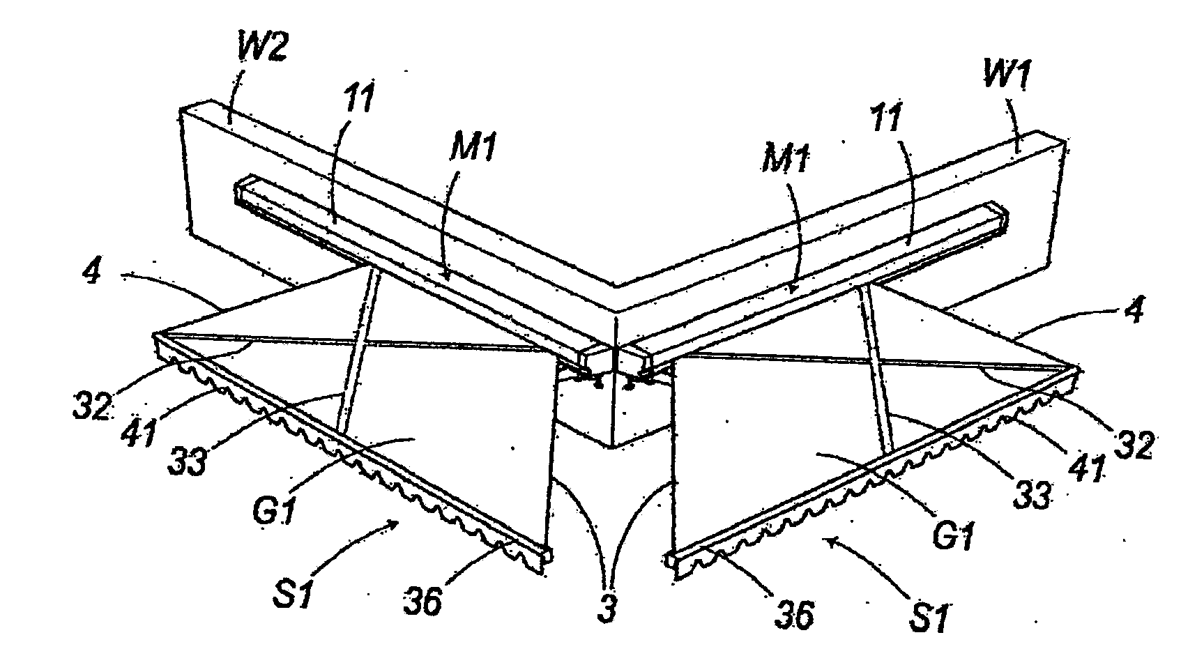
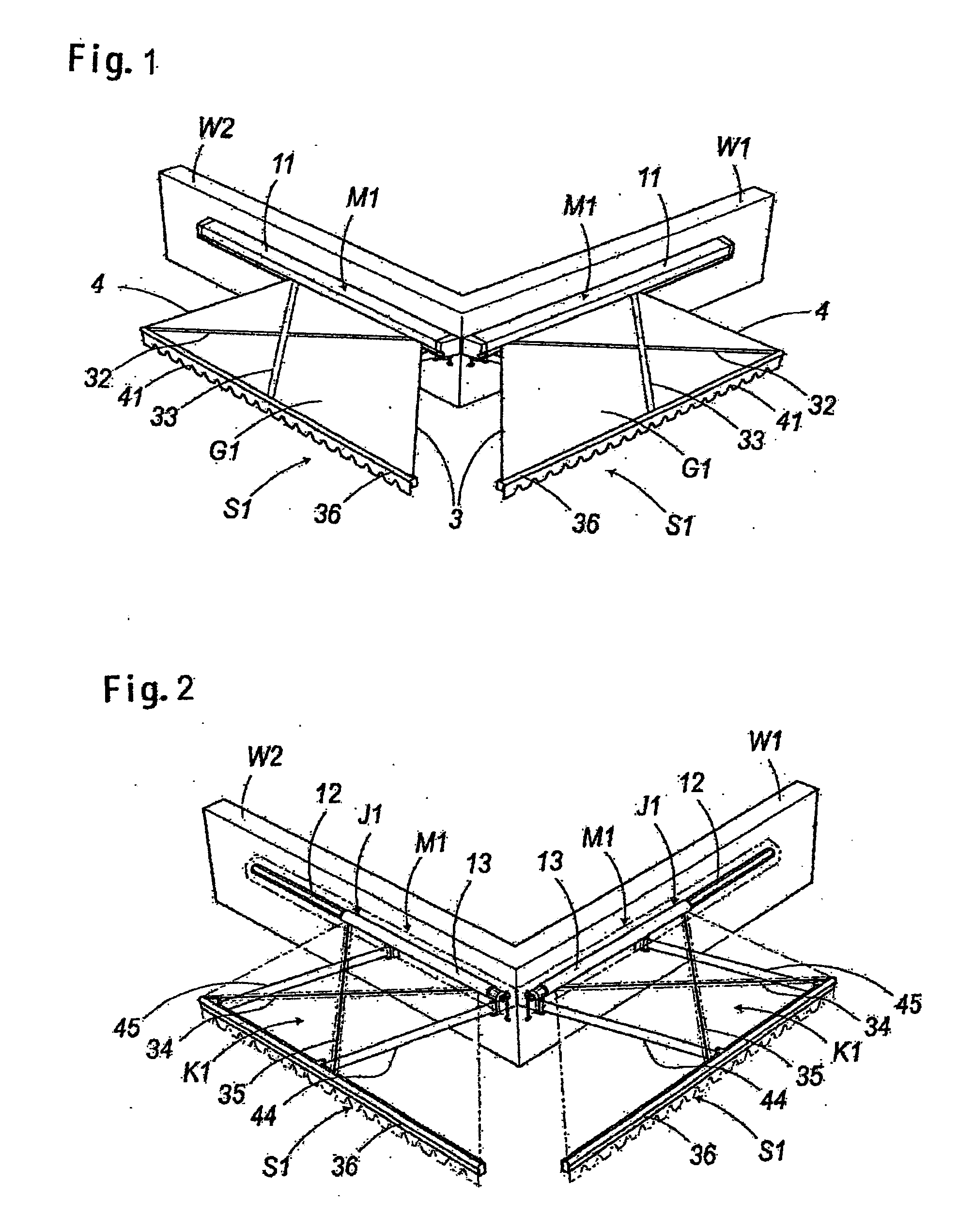
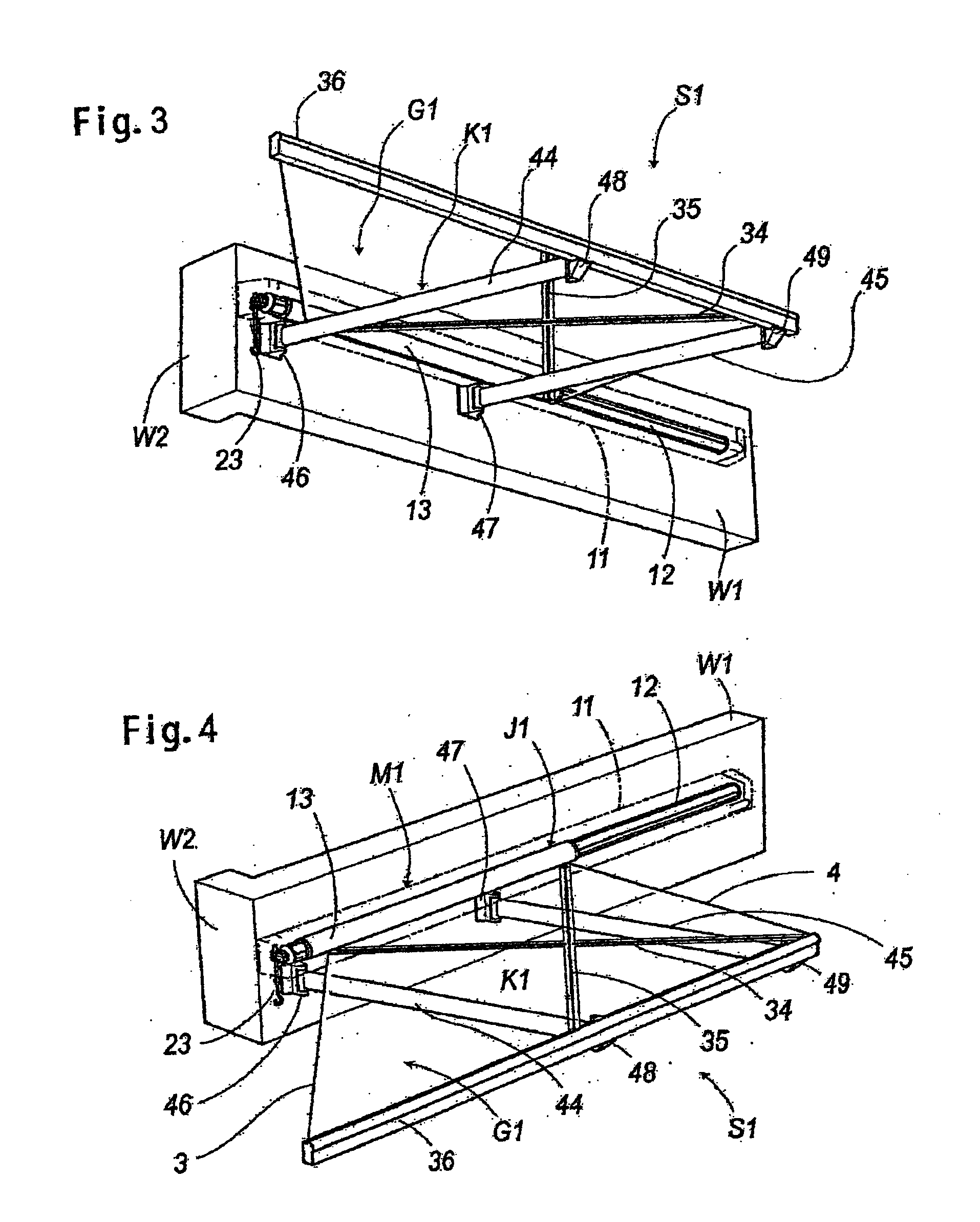
[0262]Now, I will explain the awning device S1 of the first embodiment comprising the canvas take-up device M1 of the first example and the canvas extension device K1 of the first example with reference to the attached FIGS. 1-14.

The First Example of Canvas Take-Up Device and its Take-Up Shaft

[0263]Prior to explanation of the canvas take-up device M1, I will explain the canvas take-up shaft J1 of the first example shown in FIGS. 5, 8 and 9, which is a substantial part of the canvas take-up device M1.

[0264]Reference character 11 refers to a casing for storing a wound corner canvas G1, wherein a canvas take-up shaft J1 is incorporated therein, the casing being attached on an outer wall W1-W3 in proximity to a corner of various buildings or frame structures (hereinafter “buildings”), and being fixed indirectly on the outer wall W1-W3 through an appropriate supporting bracket (not shown), or being fixed on brackets of the bottom end of various swinging arms descri...

second embodiment

of Corner Awning Device

[0364]Now, an awning device S2 of the second embodiment shown in the perspective views of FIGS. 28A-28C and FIGS. 29D and 29E, and in the plan views of FIGS. 30A-30E, is explained below.

[0365]The awning device S2 is comprised of the canvas tension device K2 of the second example having a pair of two-phase swinging arms N1, N2 in parallel, which circularly rotate in a two-phase motion, and a canvas take-up device M1 having either one of the above canvas take-up shafts J1-J5 or either one of canvas take-up shafts J6-J8 explained later.

[0366]The two-phase swinging arms N1 and N2 are each comprised of rear arm 59 and front arm 60 connected foldably. The intermediate portions of the swinging arms are connected through a connection rod 61. The arm front ends are pivoted at the brackets 48 and 49 of the front bar 36.

[0367]The brackets 46 and 47 of the bottom of the two-phase swinging arms N1, N2, that is, the bottom of the rear arm 59, are provided with a spring havi...

third embodiment

of Corner Awning Device

[0376]Now, an awning device S3 of the third embodiment shown in perspective views in FIGS. 31A and 31B, and in plan views in FIGS. 32A-32C, is explained below.

[0377]The awning device S3 is comprised of the canvas tension device K3 of the third example provided with a pair of telescopic arms T1 and T2 in parallel, which are free to expand and contract, a canvas take-up shaft M1 provided with either one of the above described canvas take-up shafts J1-J5, or a canvas take-up shaft J6-J8 described later, wherein two of the awning devices are installed at the corner of the front wall W1 and the corner of the side wall W2 in an orthogonally face-to-face relation.

[0378]In the above case, one of the canvas take-up shafts J1-J5 and the other of the canvas take-up shafts J1-J5 are configured so that both ends of the front bars 36 are fixed orthogonally in a face-to-face relation, or fixed through the connection member 67 as shown FIG. 34.

[0379]In the telescopic swinging...


PUM


Abstract

A corner canvas is formed such that when seen in a development, it has a right-angled trapezoidal form consisting of a rectangular canvas main body and a right-angled triangular canvas extension. A canvas take-up shaft is formed by an outer roller slidably and rotatably fitted on an inner shaft. When the canvas is to be developed, a folded swing arm is parallel-rotated obliquely forward and a front bar is pushed out to an obliquely forward corner space, thereby the corner space is covered. When the canvas is to be taken up, the swing arm is rotated obliquely rearward and the front bar is parallel-moved obliquely rearward, whereupon the outer roller is moved rearward while rotating to take up the corner canvas, and thereby the canvas extension is taken up by the exposed inner shaft. Thus, an epoch-making novel product is provided to the industry, which dramatically enhances ornamentality and external appearance in the corners of various buildings and which abounds in technical interests and utility as a corner awning device.

Description

[0001]The present application is a divisional application of U.S. patent application Ser. No. 11 / 615,995, filed on Dec. 25, 2006, the entire contents of which are incorporated herein by reference. The 11 / 615,995 application claimed the benefit of the date of the earlier filed PCT Application No. PCT / JP2004 / 009751 filed Jul. 1, 2004.FIELD OF THE INVENTION[0002]This invention relates to a corner awning device, and the canvas take up shaft which comprises both of said essential parts which are used for attractively covering corners of various buildings or framework structures.BACKGROUND OF THE INVENTION[0003]Conventionally, movable awning devices are configured with a combination of: a canvas take-up device, which winds or unwinds a canvas that generally extends forward at an angle from a wall, on or from a canvas take-up shaft that is supported by an outer wall of a building, by means of a manual lever or electric motor, etc., and a canvas tension device, which connects bi-foldable sw...

Claims


Application Information

Patent Timeline
Patent Type & Authority Applications(United States)
IPC IPC(8): E04F10/06E04F10/08E04F10/02
CPCE04F10/06E04F10/0685E04F10/0648E04F10/0618
Inventor ITO, OSAMU
Owner ITO OSAMU
Why Eureka
Try Eureka