Method to detect coring point from resistivity measurements

a resistivity measurement and resistivity measurement technology, applied in the direction of survey, directional drilling, wellbore/well accessories, etc., can solve the problems of not disclosing or suggesting the use of resistivity measurement, reducing the effectiveness or negating the purpose of resistivity measurement, and the coring system in use today is not designed. , to achieve the effect of minimizing the coring

Inactive Publication Date: 2010-01-07
BP CORP NORTH AMERICA INC
View PDF36 Cites 50 Cited by
  • Summary
  • Abstract
  • Description
  • Claims
  • Application Information

AI Technical Summary

Benefits of technology

[0018]In certain embodiments, the method comprises using the identification of the top of the region of the formation to obtain a core. In certain embodiments this may comprise tripping the drill string out of the well to detach a drill bit or assembly and attach a coring assembly including a coring bit, tripping the dr

Problems solved by technology

This exposure presents problems, including the fact that the condition of the borehole itself and surrounding disturbed formation will have an effect on the very resistivity values being sought, as noted by Hottman et al., “Estimation of Formation Pressures From Log-Derived Shale Properties”, SPE 1110 (1965).
However, Banning et al. do not disclose or suggest use of resistivity measurements in front of a drilling bit to detect a top of a region of interest of a formation and make core drilling decisions to obtain a whole core before the bit exposes the formation to the drilled wellbore.
Most coring systems in use today are not designed

Method used


Image

  • Method to detect coring point from resistivity measurements
  • Method to detect coring point from resistivity measurements
  • Method to detect coring point from resistivity measurements

Examples


embodiment 300

[0048]In accordance with the present disclosure, as illustrated in FIG. 3A, the lower toroid 130 is placed down at the tip of the bit 110, or very near thereto. In such embodiments the rock being investigated will be increasingly moved forward ahead of the bit 110, as illustrated schematically in FIG. 3B. While this may seem to be a subtle change, the result is much greater ability to focus the resistivity measurements in front of the drill bit, and allow the top of a region of interest for coring to be detected and appropriate preparations made to obtain a whole core sample prior to the bit entering the region. FIG. 3C illustrates a method in accordance with this disclosure, illustrating schematically in embodiment 300 including an offset well 112a from which resistivity data has been previously gathered using conventional methods from a region of interest 90 in the formation previously drilled using drillstring 101 and drill bit 110 (both illustrated in phantom in FIG. 3C). A well...

embodiment 400

[0050]In accordance with the present disclosure, transient electromagnetic survey techniques and apparatus normally used in marine surveys may be modified to be deployed within a well 112, as illustrated schematically in embodiment 400 of FIG. 4. A dipole transmitter 402 is mounted on the drill string behind the drill bit 110, and EM receivers 404 and 406 are mounted below the dipole. The EM receivers 404, 406 measure a normally reflected wave in the axis of the drill string. This normally reflected wave would be off of resistivity contrasts directly in front of the bit. This would work very much like an acoustic VSP but working in the electromagnetic spectrum.

[0051]Another method to make a resistivity measurement in front of the bit would be to use modified continuous deep directional electromagnetic measurements. Deep directional electromagnetic (EM) tool measurements are known and explained, for example, in Omeragic et al., “Deep Directional Electromagnetic Measurements for Optim...

embodiment 800

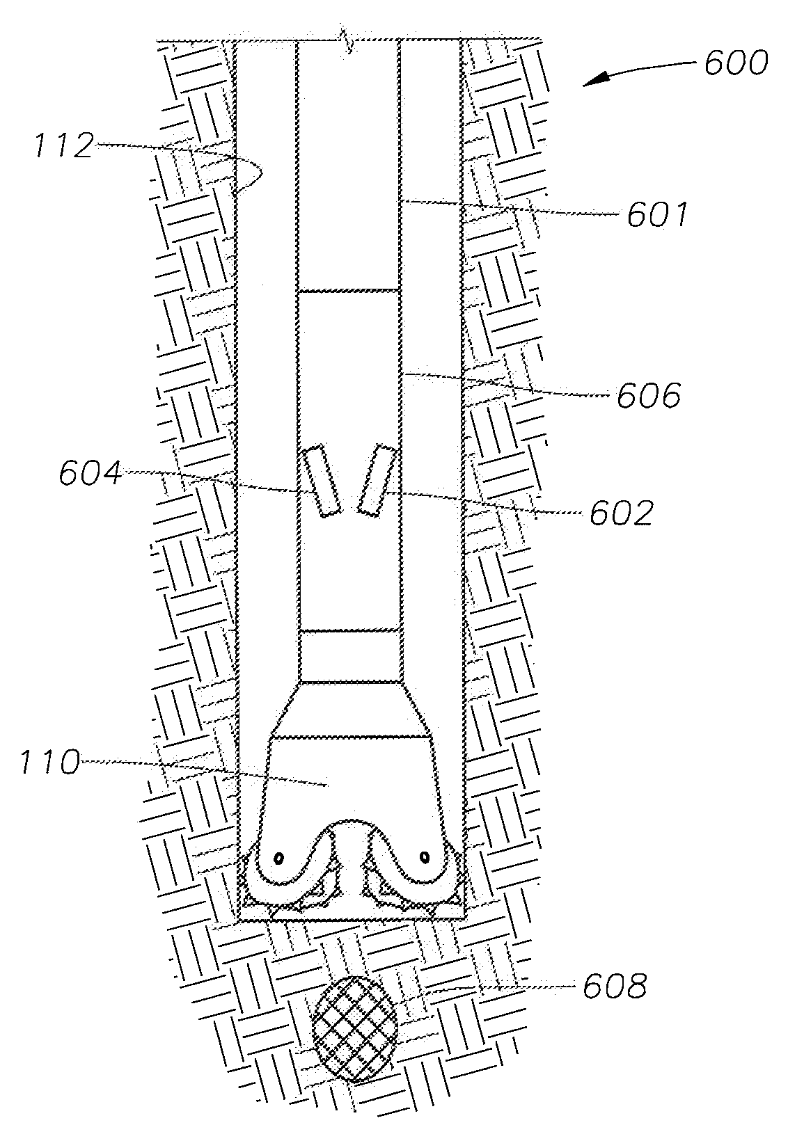
[0054]FIG. 8 illustrates an embodiment 800 modified to focus energy in front of the bit and measure the formation resistivity ahead of the drill bit. Rather than sensing an oil / water contact, the reflected waves 85 would be reflected off of the top of a region of interest 90, containing perhaps, but not necessarily, hydrocarbons.

[0055]In accordance with the present disclosure, a primary interest lies in using one or more of the methods and apparatus described above to obtain resistivity measurements in front of the drill or core bit to determine a top of a region of interest in the formation in order to obtain a whole core of the region before the bit exposes the formation, which as discussed may create undesirable consequences in the well. The skilled operator or designer will determine which resistivity method and apparatus is best suited for a particular well and formation to achieve the highest efficiency without undue experimentation.

[0056]Useful drilling muds for use in the me...


PUM


Abstract

Methods are described using resistivity ahead of a drill bit measurements obtained while drilling a subterranean well using a drilling mud. Resistivity data ahead of the bit is gathered during drilling and prior to penetrating a region of interest of a target subterranean formation using the drill bit and the drilling mud. The drill string progresses at target dip and azimuth angles toward the region on interest. The resistivity data is used to determine the top of the region of interest while the drill bit advances toward but does not penetrate the region. A core bit is then installed and a whole core of the region of interest obtained. Resistivity ahead of a drill bit measurements obtained while drilling a subterranean well may also be compared with conventional resistivity measurements obtained from one or more offset wells.

Description

CROSS-REFERENCE TO RELATED APPLICATIONS[0001]The present application is related to U.S. application Ser. Nos. ______ and ______, filed on even date herewith, and which are incorporated herein by reference in their entirety.BACKGROUND INFORMATION[0002]1. Technical Field[0003]The present disclosure relates in general to methods for drilling wells in subterranean formations, and more particularly to methods of using resistivity data to identify a top of a formation, while the drill bit advances toward but does not penetrate the formation, in order to obtain a whole core from the formation.[0004]2. Background Art[0005]Formation resistivity measurements are commonly made in oil and gas wells and then used to make decisions about the presence of hydrocarbons, the magnitude of pore pressure, the correlation to formations observed in offset wells, the salinity of formation fluids, porosity of formations, and the presence of permeability. FIG. 1 illustrates graphically the prior art concept ...

Claims


Application Information

Patent Timeline
IPC IPC(8): E21B47/026E21B49/00E21B7/04
CPCE21B47/026E21B49/02E21B49/00
Inventor ALBERTY, MARK WILLIAM
Owner BP CORP NORTH AMERICA INC
Why Eureka
Try Eureka