Eureka AIR delivers breakthrough ideas for toughest innovation challenges, trusted by R&D personnel around the world.

Method of manufacturing an elongated glass body

a manufacturing method and glass body technology, applied in glass reforming apparatus, glass making apparatus, manufacturing tools, etc., can solve the problems of reducing the precision of the post-elongation outer diameter, the difficulty of obtaining the desired refractive index profile at each position along the longitudinal direction,

Inactive Publication Date: 2010-01-14
SUMITOMO ELECTRIC IND LTD
View PDF2 Cites 3 Cited by
  • Summary
  • Abstract
  • Description
  • Claims
  • Application Information

AI Technical Summary

Benefits of technology

The present invention relates to a method for manufacturing an elongated glass body with a desired refractive index profile and outer diameter. The method involves softening the glass body and elongating it to have a target outer diameter. The method includes two elongating steps: a first step for obtaining an intermediate elongated body with a larger outer diameter than the target outer diameter, and a second step for elongating the intermediate elongated body to have the target outer diameter. The method ensures that the outer diameter of the elongated glass body is uniform in the longitudinal direction. The invention also addresses the problem of degradation in the precision of the outer diameter caused by heating during the elongation process.

Problems solved by technology

However, with the method disclosed in that invention, the outer diameter of the elongated optical fiber preform varies in the longitudinal direction very much, resulting in difficulty of obtaining a desired refractive index profile at each position along the longitudinal direction.
Accordingly, the outer diameter is decreased, resulting in degradation in the precision of the post-elongation outer diameter.
These problems arise not only in the process of elongating the intermediate preform during the manufacturing process of an optical fiber preform, but also in the process of elongating a columnar or cylindrical glass body in general.

Method used


Image

  • Method of manufacturing an elongated glass body
  • Method of manufacturing an elongated glass body
  • Method of manufacturing an elongated glass body

Examples


examples

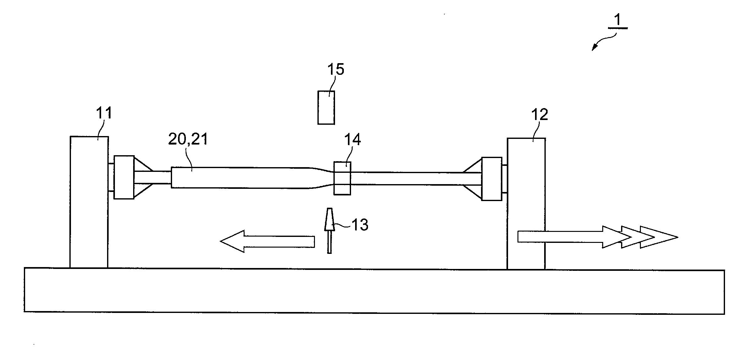
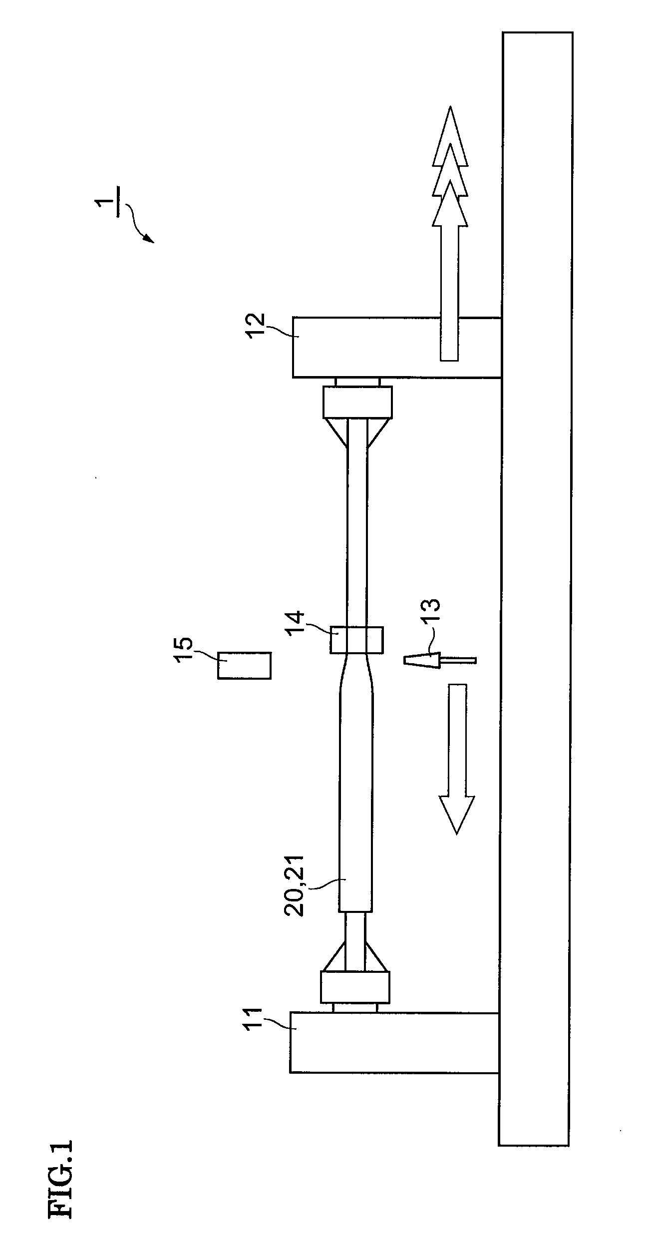
[0031]Below, more concrete examples will be described. In the first example, the elongation machine 1 shown in FIG. 1 was used in a manner such that a dummy rod was melt-bonded to each end of the glass body 20 and these dummy rods were held by holding parts 11 and 12. The glass body 20, which was mainly made of silica glass, had a columnar shape for elongation, initially having a length of about 600 mm and an outer diameter of 30 mm. The target outer diameter D2(X) of an elongated glass body to be achieved was uniformly set to 10 mm regardless of X in the longitudinal direction.

[0032]An oxyhydrogen burner was used as the heating source 13, and the distance between the glass body 20 and the oxyhydrogen burner was set so that the quantity flame-polished by heating (the quantity of the circumferential portion of the glass body that is scraped off by the oxyhydrogen flame) might be smaller. The diameter monitor 14 was arranged on the rear side of the heating source 13 with respect to th...


PUM

PropertyMeasurementUnit
temperatureaaaaaaaaaa
outer diameteraaaaaaaaaa
diameteraaaaaaaaaa

Abstract

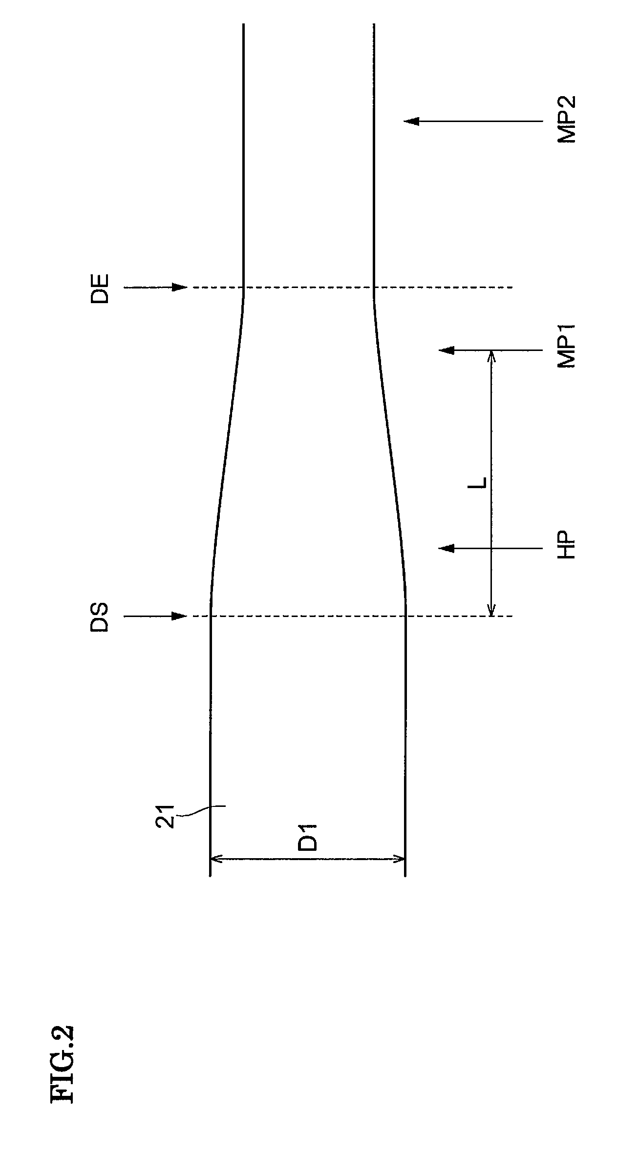
A method of manufacturing an elongated glass body by elongating a glass body of columnar or cylindrical shape. The method comprises: (1) a first elongating step for obtaining an intermediate elongated body, where the glass body is softened by heating and elongated, while the diameter of the softened part is measured, so that the measured value may become equal to a first controlled diameter which is larger than the target diameter, where the diameter of the intermediate elongated body satisfies the relationship at each position thereof: (the target diameter−10 μm)<(the diameter of the intermediate elongated body)<(the target diameter+500 μm); and (2) a second elongating step for obtaining an elongated glass body having the target diameter, where the intermediate elongated body is softened by heating and elongated.

Description

TECHNICAL FIELD[0001]The present invention relates to a method of manufacturing an elongated glass body.BACKGROUND ART[0002]An optical fiber that is manufactured by drawing an optical fiber preform has characteristics that depend on the refractive index profile along the radius of the preform. As the required precision of the characteristics of an optical fiber has become higher, so has the precision required of the refractive index profile of the optical fiber become higher. Thus, in order to respond to such requirement, there has been a demand for a method with which an optical fiber preform having a desired refractive index profile can be manufactured.[0003]Also, higher precision is required in the elongation process of an intermediate preform, which is one step of the process for manufacturing an optical fiber preform. WO2004 / 000740 (Patent Document 1) discloses an invention for controlling the elongation rate on the basis of the outer diameter of an intermediate preform as meas...

Claims


Application Information

Patent Timeline
Patent Type & Authority Applications(United States)
IPC IPC(8): C03B37/07
CPCC03B23/047C03B37/01242C03B37/0124
Inventor NAKANISHI, TETSUYAHISHIKURA, RYOUJI
Owner SUMITOMO ELECTRIC IND LTD
Why Eureka
Eureka Blog
Learn More