
Method for improving display lifetime

Active Publication Date: 2010-01-14
GLOBAL OLED TECH
View PDF20 Cites 8 Cited by
  • Summary
  • Abstract
  • Description
  • Claims
  • Application Information

AI Technical Summary

Benefits of technology

[0011]b. lowering the intensity value of the first subpixel in each pixel and still providing an acceptable pixel color to an observer.
[0012]It is an advantage of this invention that it can extend the lifetime of an electroluminescent display while providing acceptable color to an observer. Other advantages, including a reduction in display power consumption and improved image quality can also result.

Problems solved by technology

Unfortunately, increasing the current density used to drive an OLED, and therefore the luminance, not only increases the power required to drive the OLED but also reduces the lifetime of the OLED.
This differential color output change will change the color balance of the display, such that images may have a serious color imbalance, which is much more noticeable than a decrease in overall luminance.
Alternatively, one can reduce the luminance of the more robust colors, but this lowers the overall brightness of the display.
In some display configurations, the available red OLED materials have significantly lower luminous efficiency than the existing green and blue OLED materials.
However, optimizing the display layout suggested by Kim et al., does not necessarily lead one to a design in which the lifetimes of the three materials are optimized.
However, Yamada fails to discuss other important characteristics of OLED materials that will affect device lifetime, such as the differences in the inherent luminance stability over time of different materials.
More importantly, typical manufacturing approaches limit the maximum differences in the areas of the different colored subpixels.
As such, this approach alone cannot compensate for all of the differences in emission efficiency of the materials, or for other important factors, such as optical characteristics or differences in the inherent luminance stability of the different materials that are typically used to form the differently colored subpixels.

Method used


Image

  • Method for improving display lifetime
  • Method for improving display lifetime
  • Method for improving display lifetime

Examples


Embodiment Construction

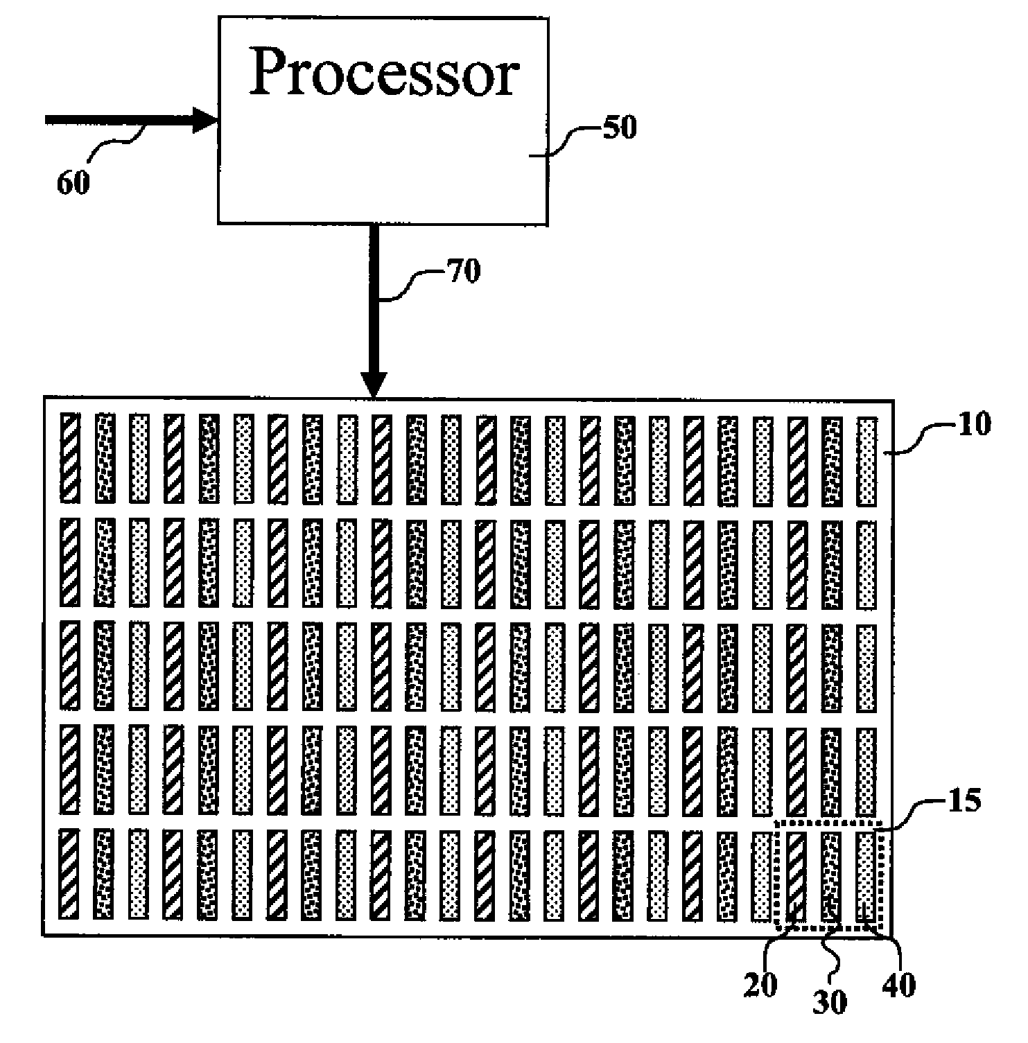
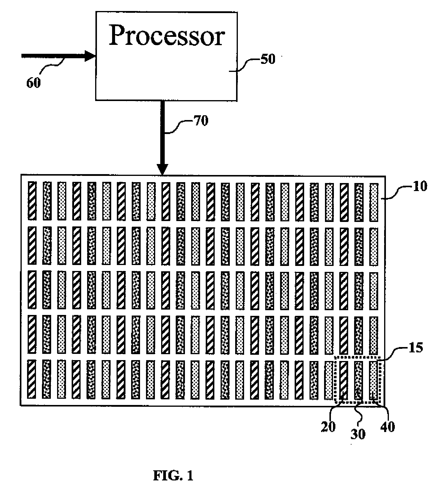
[0015]Turning now to FIG. 1, there is shown one embodiment of a display that can be used in the practice of this invention. The display can include an electroluminescent (EL) display 10, such as an OLED display, and a controller 50 for providing the method of the present invention. Controller 50 can be any one or combination of digital or analog processors capable of receiving an input image signal 60, processing the input image signal, and providing a drive signal 70 to drive EL display 10. EL display 10 includes an array of colored pixels 15, wherein each pixel includes at least a first subpixel 20, a second subpixel 30, and a third subpixel 40, each of which emits light of a different color, e.g. blue, green, and red subpixels.

[0016]It is often seen that one of the colored subpixels, e.g. first subpixel 20, has a lower or shorter lifetime than the lifetimes of the other colored subpixels when all the subpixels are driven to equivalent luminance values, e.g. the luminance values r...


PUM


Abstract

A method for adjusting the intensity values of colored pixels wherein each pixel has a first subpixel, a second subpixel, and a third subpixel, wherein each of the subpixels emits light of a different color and the lifetime of the first subpixel is lower than the lifetimes of the other colored subpixels, comprising: for each pixel, receiving intensity values corresponding to the intensity of each color subpixel in each pixel; and lowering the intensity value of the first subpixel in each pixel and still providing an acceptable pixel color to an observer.

Description

FIELD OF THE INVENTION[0001]The present invention relates to light-emitting displays and a method for improving the lifetime of such displays.BACKGROUND OF THE INVENTION[0002]Many emissive display devices exist within the market today. Among the displays that are available are thin-film, coated, electro-luminescent displays, such as Organic Light-Emitting Diode (OLED) displays. These displays can be driven using active matrix backplanes, which employ an active circuit, or passive matrix backplanes, which provide common signals to rows and columns of light-emitting elements.[0003]In typical, prior-art OLED displays, it is known that the luminance of the different color emitters, e.g. red, green, and blue OLEDs, increases as current density delivered to the OLED is increased. The transfer function from current density to luminance typically behaves according to a linear function. Therefore, to increase the luminance of the display, one must increase the current delivered to an OLED wi...

Claims


Application Information

Patent Timeline
IPC IPC(8): G09G3/30
CPCG09G3/3216G09G3/3225G09G2300/0452G09G2340/06G09G2320/0276G09G2320/043G09G2330/021G09G2320/0242G09G3/30G09G3/32
Inventor MILLER, MICHAEL E.
Owner GLOBAL OLED TECH
Learn More