Ophthalmoscope

a technology which is applied in the field of opthalmoscope, can solve the problems of deteriorating image sharpness, difficult to examine the background of the eye with the aid of illumination beam, and difficult to achieve the effect of ophthalmoscope and eye background examination

Active Publication Date: 2010-01-14
OD OS
View PDF5 Cites 27 Cited by
  • Summary
  • Abstract
  • Description
  • Claims
  • Application Information

AI Technical Summary

Benefits of technology

[0010]An opthalmoscope includes an electronic system for excluding stray light from the observation beam including an electronic drive circuit for reading out at least one pixel row of the sensor The opthalmoscope comprises an electronic control unit which is adapted to control the scanning means and the electronic drive circuit so that the scanning of the illumination beam over the eye is synchronous with the change of the pixel row currently to be read out.

Problems solved by technology

Imaging of the eye background, for example the retina, constitutes an optical challenge in this regard since both the illumination and the observation of the eye background is carried out through a comparatively small entry pupil of the eye.
Optical examination of the eye background with the aid of an illumination beam, which is examined as an observation beam after reflection for example from the retina, is moreover made difficult by undesired further reflections from the interfaces of the cornea as well as by undesired light scattering for example from vitreous body turbidities.
In practice, however, it has been found that particularly the selection of a metal sheet which has a slit shutter and oscillates in front of the sensor leads to problems.
This is because on the one hand the oscillations of the mechanical oscillator for the metal sheet can be decoupled only insufficiently from the housing of the instrument, which generally entails difficulties in handling the opthalmoscope and in particular degradations of the image sharpness owing to co-vibration of the sensor.
It is nevertheless compulsory to maintain a certain minimum distance of the metal sheet oscillating from the sensor, which inevitably leads to inferior suppression of perturbing stray light.

Method used


Image

  • Ophthalmoscope
  • Ophthalmoscope
  • Ophthalmoscope

Examples


Embodiment Construction

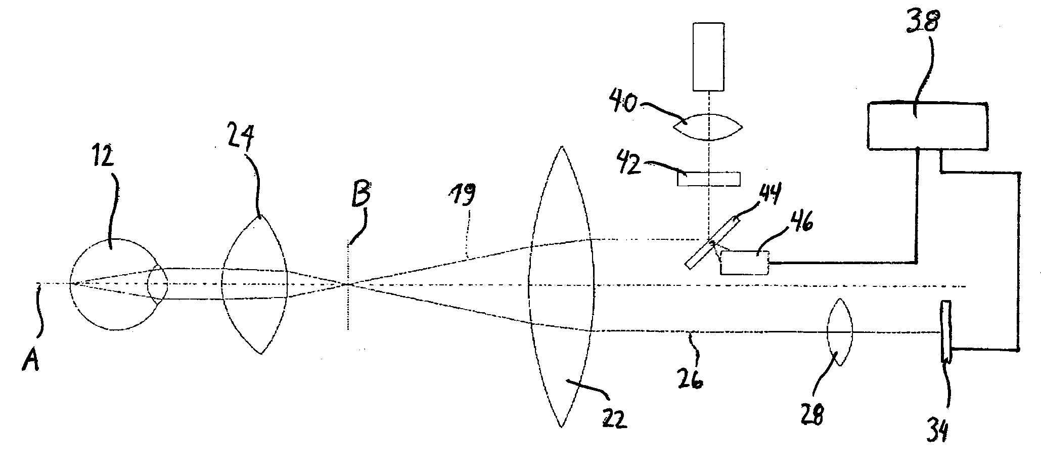
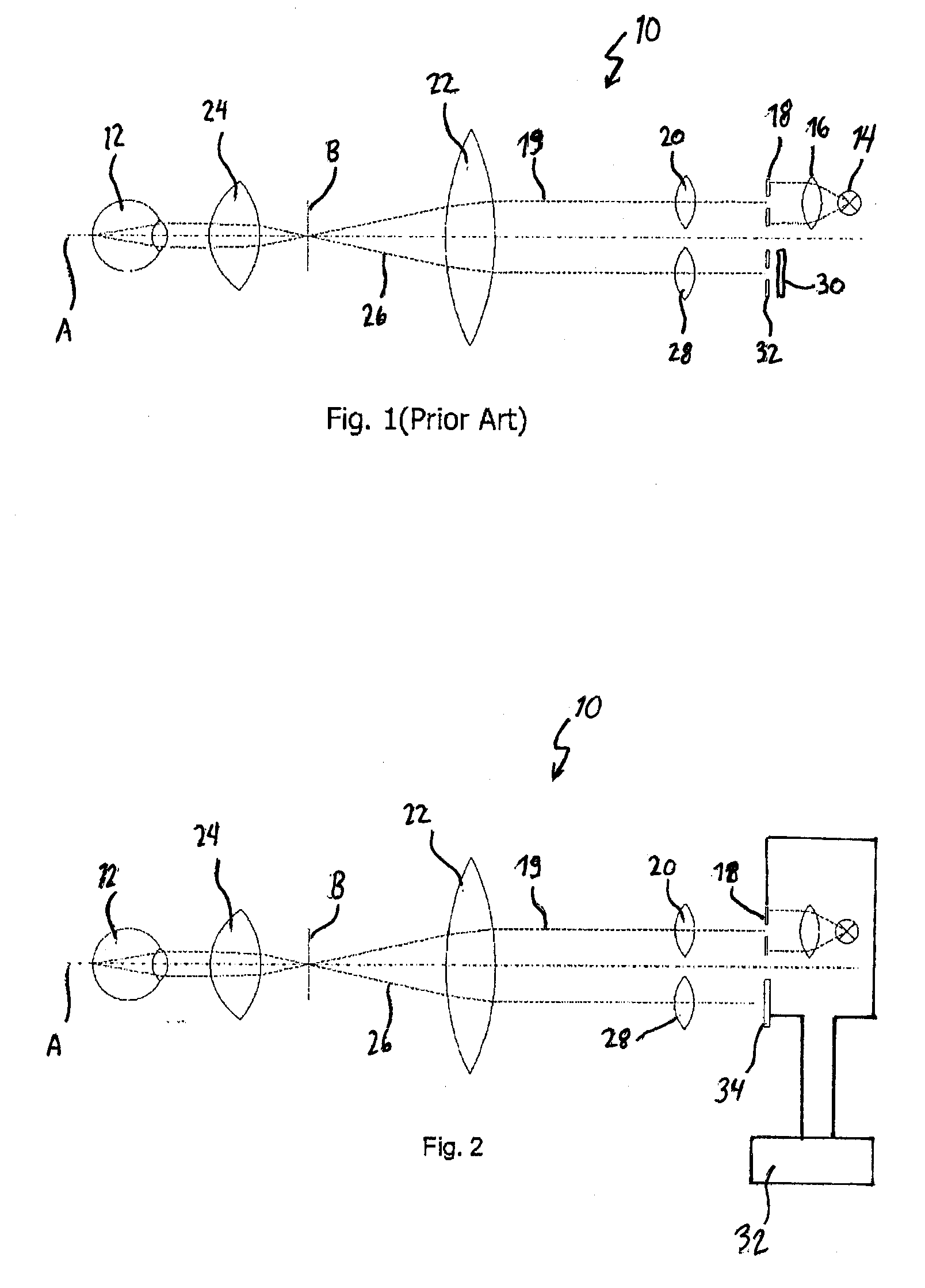
[0026]FIG. 1 shows a schematic representation of an opthalmoscope 10 of the prior art for studying a patient's eye 12. The light emitted by an illumination device 14 is collimated by means of a condenser 16 and strikes a slit shutter 18 which oscillates, specifically in a direction perpendicular to the optical axis A of the opthalmoscope 10 in the plane of the drawing in the schematic representation of FIG. 1. This slit shutter 18 is oriented perpendicularly to the plane of the drawing.

[0027]A line, the length and thickness of which is defined by the shape of the slit shutter 18 and whose position depends on the current location of the oscillating slit shutter, is thereby extracted from the flat light spot onto which the condenser 16 has collimated the light of the illumination device 14.

[0028]Using further lenses 20, 22, the illumination beam 19 is focused into an intermediate image plane B, from which it is imaged through an opthalmoscopic lens 24 onto the eye 12. The schematic re...


PUM


Abstract

An opthalmoscope for examining a patient's eye includes an illumination device for generating an illumination beam Illumination imaging optics image the illumination beam onto the eye, and a scanning device scans the illumination beam over the eye. The opthalmoscope also includes an observation device and observation imaging optics for imaging an observation beam generated by reflection of the illumination beam from the eye onto the observation device. An electronic shutter excludes stray light from the observation beam. The observation device comprises an electronic sensor with an array of photosensitive pixels that can respectively be activated and/or read out in rows, and the scanning device includes an electronic drive circuit for reading out at least one pixel row of the sensor.

Description

FIELD OF THE INVENTION[0001]The present invention relates to an opthalmoscope for examining a patient's eye.BACKGROUND[0002]An opthalmoscope is used to observe the patient's eye background, for example for retinal examinations. An opthalmoscope delivers high-resolution color or black-and-white images in continuous succession, so that it can be used to diagnose the eye as well as for carrying out and documenting therapeutic interventions. Imaging of the eye background, for example the retina, constitutes an optical challenge in this regard since both the illumination and the observation of the eye background is carried out through a comparatively small entry pupil of the eye. The eye background furthermore generally has only a weak reflectivity, which dominates for red color components, so that high-contrast color images of the eye background can in general be produced only by a light source with strong blue and green components.[0003]Optical examination of the eye background with th...

Claims


Application Information

Patent Timeline
Patent Type & Authority Applications(United States)
IPC IPC(8): A61B3/15A61B3/12
CPCA61B3/158A61B3/12
Inventor LIESFELD, BENTEIWES, WINFRIEDHUPPERTZ, MICHAELAMTHOR, KAY-UWE
Owner OD OS
Why Eureka
Try Eureka