Engine and method for improved crankcase fatigue strength with fracture-split main bearing caps

Active Publication Date: 2010-01-21
GM GLOBAL TECH OPERATIONS LLC
View PDF8 Cites 2 Cited by
  • Summary
  • Abstract
  • Description
  • Claims
  • Application Information

AI Technical Summary

Benefits of technology

[0004]The present invention solves the problem presented by lowering the outer edges of the crankshaft bearing cap split line without changing the central axis location of the crankshaft in the crankcase. This is accomplished by causing the split lines of the bearing caps to angle downward from the horizontal plane of the crankshaft axis to a slightly lower position at the o

Problems solved by technology

The larger section would be impossible to

Method used


Image

  • Engine and method for improved crankcase fatigue strength with fracture-split main bearing caps
  • Engine and method for improved crankcase fatigue strength with fracture-split main bearing caps
  • Engine and method for improved crankcase fatigue strength with fracture-split main bearing caps

Examples


Example

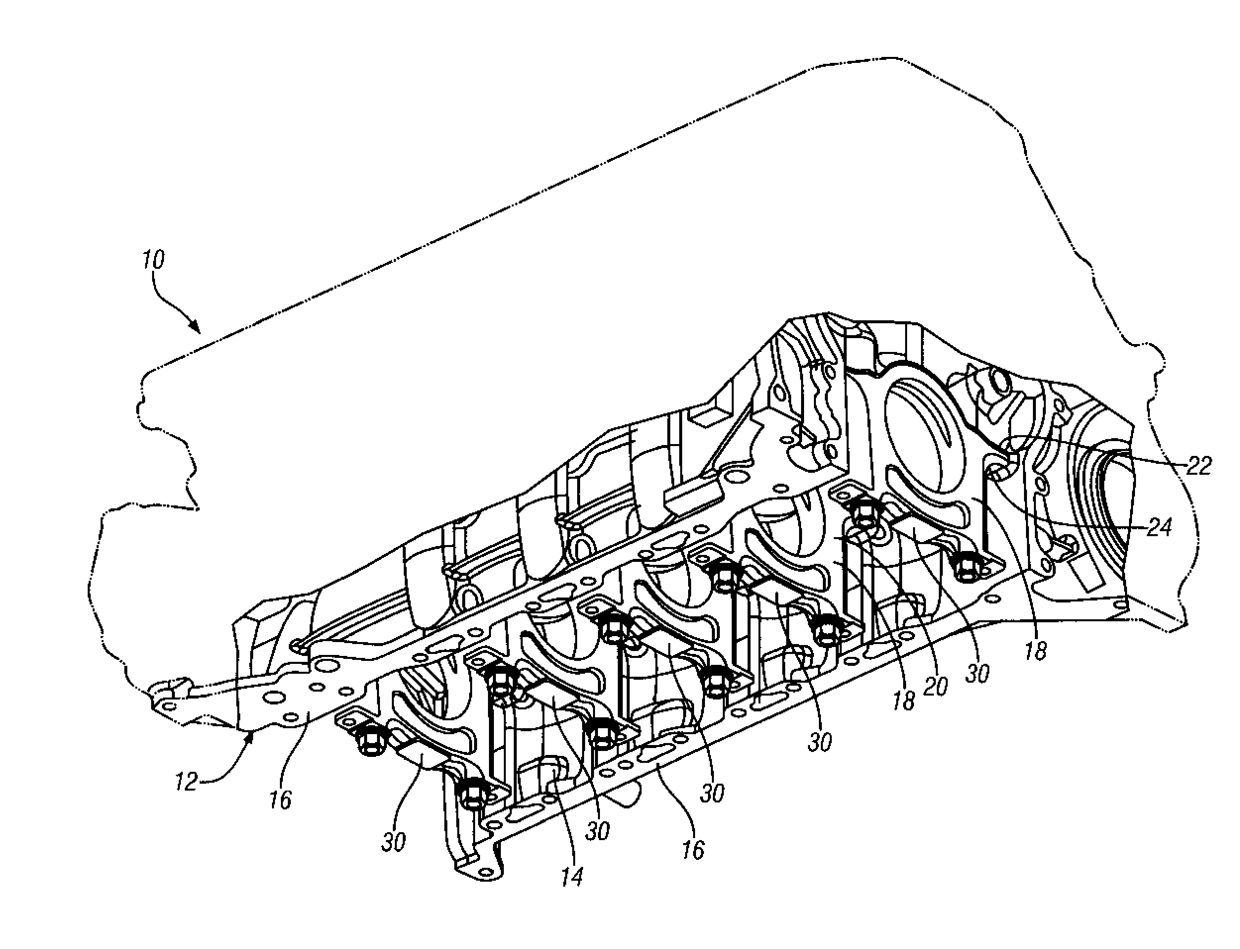
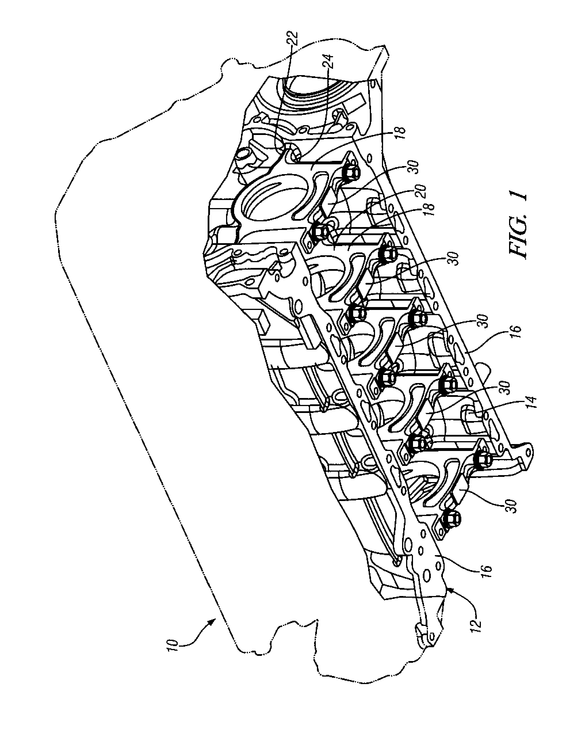
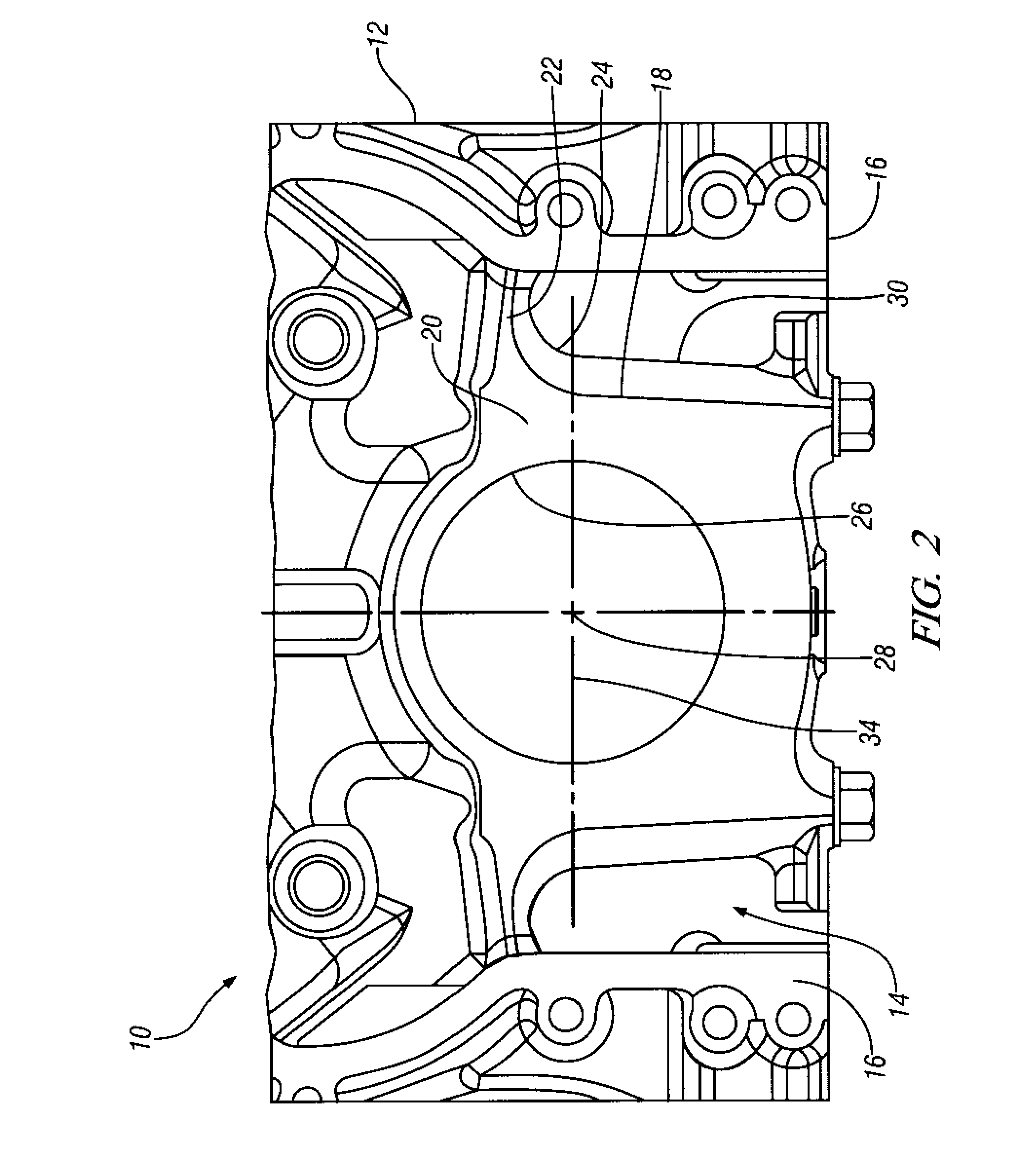
[0013]Referring now to FIGS. 1 and 2 of the drawings in detail, numeral 10 generally indicates an outline view of an exemplary internal combustion engine having a cylinder block 12 in which pertinent details of the structure in a lower portion of the engine crankcase 14 are disclosed. The lower crankcase 14 includes a pair of generally parallel longitudinally extending sidewalls 16 having a plurality of longitudinally spaced laterally extending web walls 18 including upper portions 20 that are attached to the sidewalls 16 by load carrying lateral connectors 22. To minimize fatigue stresses, the connectors are provided with substantial blend radii 24 connecting the upper portions 20 of the web walls 18 with the sidewalls 16.

[0014]In manufacture, the engine cylinder block 12 is cast and machined to finished dimensions as a one piece assembly. Machining includes boring of crankshaft bearing bores 26 aligned on an axis 28 in the lower portions of the web walls 18. After machining, the c...


PUM

PropertyMeasurementUnit
Diameteraaaaaaaaaa
Fatigue strengthaaaaaaaaaa
Stress concentration factoraaaaaaaaaa

Abstract

The present invention provides reduced fatigue stress levels in a stressed area of an engine crankcase by lowering the outer edges of the crankshaft bearing cap fracture-split lines without changing the central axis location of the crankshaft in the crankcase. This is accomplished by causing the fracture-split lines of the bearing caps to angle downward from the horizontal plane of the crankshaft axis to a slightly lower position at the outer edges of the bearing caps. This lowers the outer edges of the bearing caps sufficiently to allow larger radii to be formed on the lateral connectors of the crankcase support webs with the adjacent sidewalls of the crankcase. Accordingly, the fatigue stress levels in the crankcase web members are reduced without requiring a significant change in the crankcase dimensions.

Description

TECHNICAL FIELD[0001]This invention relates to engine block structure and particularly to the reduction of fatigue stresses in the crankcase web areas above fracture-split crankshaft bearing caps.BACKGROUND OF THE INVENTION[0002]It is known in the art relating to engine crankcases that crankshaft support webs are required to absorb major stresses from the combustion and inertia loads developed in the engine cylinders and from the reciprocating and rotating masses connected to the crankshaft throws. To withstand these loads, engine crankcases and cylinder blocks may be formed as a single casting and machined with the crankshaft bearing caps in place. The bearing caps are then cracked off with a mandrel, leaving a generally horizontal split line of cracked surfaces at which the bearing caps are reattached to the crankcase with bolts or studs.[0003]To minimize stresses, joining of the support webs to crankcase sidewalls makes use of smoothly curved joints avoiding sharp angles which wo...

Claims


Application Information

Patent Timeline
IPC IPC(8): B21K3/00
CPCB23D31/003Y10T29/49234F02F7/0053Y10T29/49789Y10T29/4979Y10T29/49231
Inventor WIEBRECHT, ERIC DONALD
Owner GM GLOBAL TECH OPERATIONS LLC
Why Eureka
Try Eureka