
A method for obtaining maximum energy tracking of natural flow field

A technology with the largest energy and nature, applied in the direction of complex mathematical operations, etc., can solve the problems of extra hardware investment in the energy capture direction of the natural flow field, long correction and compensation implementation period, poor universality, etc.

Pending Publication Date: 2019-01-29
SHANGHAI ELECTRIC WIND POWER GRP CO LTD
View PDF0 Cites 2 Cited by
  • Summary
  • Abstract
  • Description
  • Claims
  • Application Information

AI Technical Summary

Problems solved by technology

[0008] The purpose of the present invention is to propose a method for obtaining the maximum tracking of natural flow field energy. This method is a general method that can realize the maximum energy capture of flow field energy conversion equipment groups without adding additional equipment investment, and can solve the problem of equipment group Maximization of group energy capture faces problems such as long correction and compensation implementation cycle, poor universality, and additional hardware investment, and effectively solves the problem of inaccurate energy capture directions in natural flow fields

Method used


Image

  • A method for obtaining maximum energy tracking of natural flow field
  • A method for obtaining maximum energy tracking of natural flow field

Examples


Embodiment 1

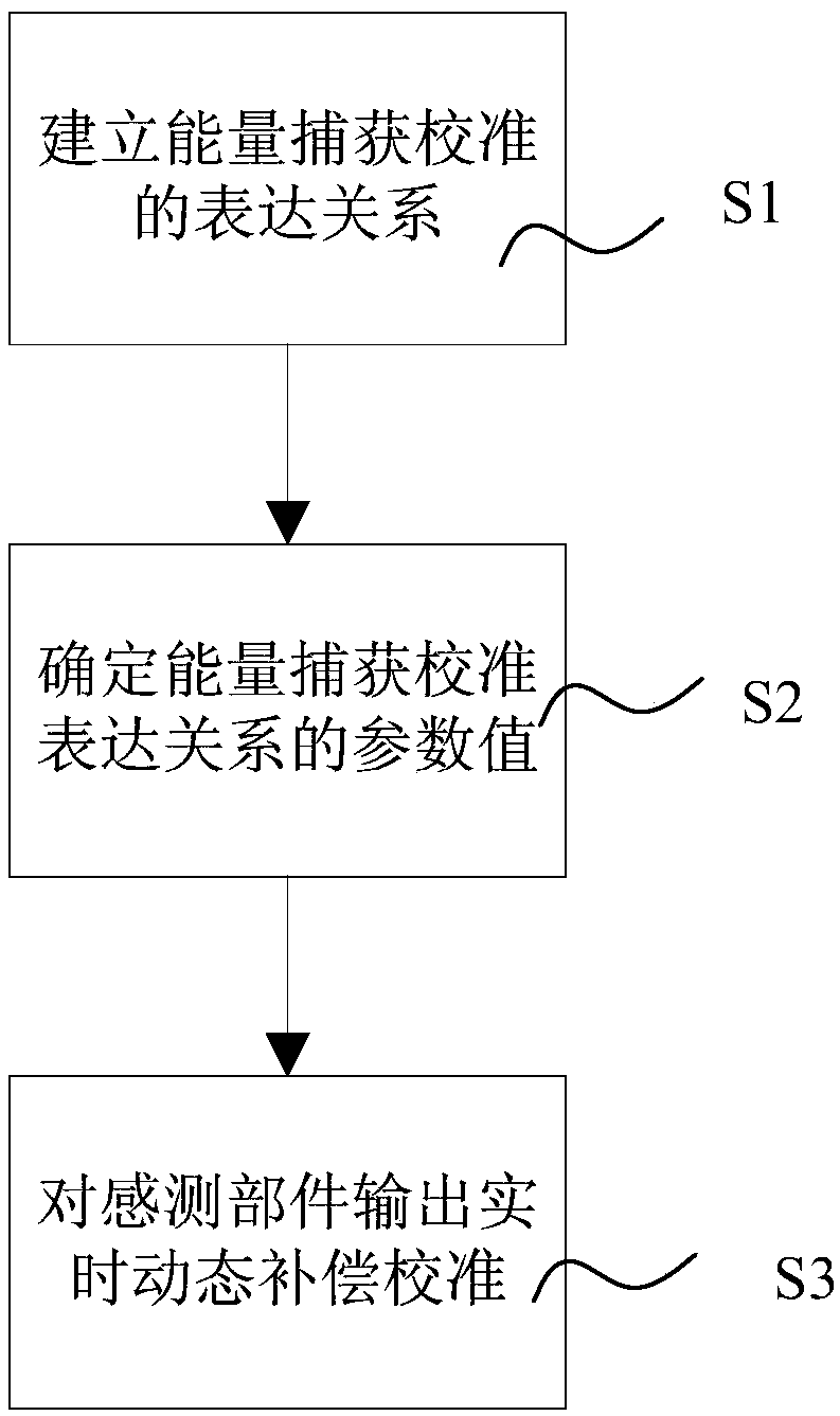
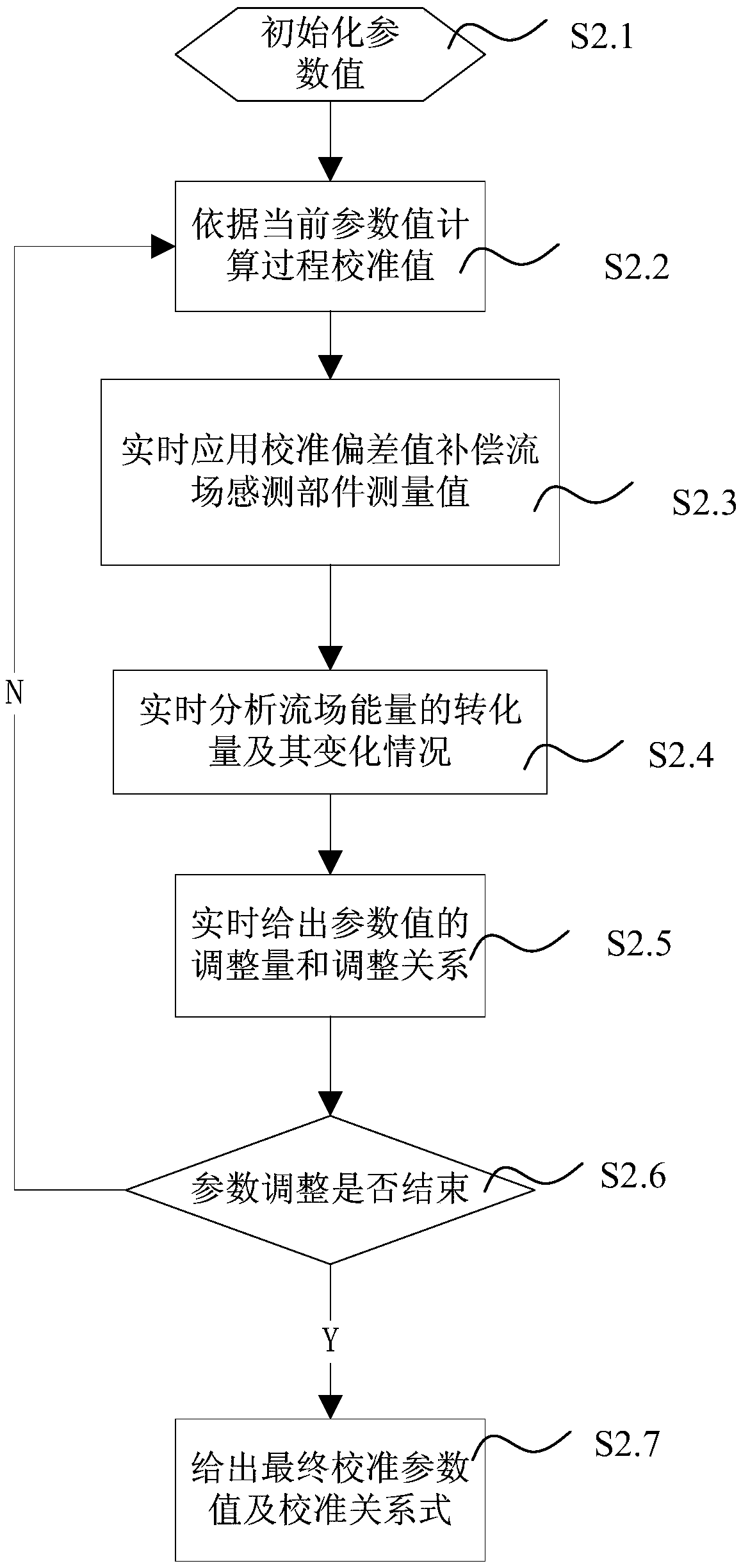
[0041] like figure 1 and figure 2 As shown in combination, in the first embodiment of the method for obtaining the maximum tracking of natural flow field energy described in the present invention, the following implementation steps are included:

[0042] T1. Establish an expression relationship for energy capture calibration:

[0043] Described step T1 further comprises:

[0044] T1.1. Determine the influencing factors of energy capture in the flow field;

[0045] Among them, the flow field sensing component used in the energy conversion equipment system is actually installed at the position behind the energy capture rotating component, and is disturbed by the rotating flow field caused by the energy capture rotating component; and most of the flow field sensing components are installed without calibration equipment. , there are deviations caused by installation errors. The deviation originates from the complex dynamic effect of the flow field, and the deviation caused by...

Embodiment 2

[0070] like figure 1 and figure 2 As shown in combination, the second embodiment of a method for obtaining maximum tracking of natural flow field energy according to the present invention includes the following implementation steps:

[0071] P1, establish the expression relationship of energy capture calibration;

[0072] Described step P1 further comprises:

[0073] P1.1. Determine the influencing factors that affect the energy capture of the flow field;

[0074] Among them, based on the expert experience of the operating conditions of the energy conversion equipment system, it is determined that the complex influencing factors of the energy capture of the flow field include: the rotation effect of the rotating parts, the initial deviation caused by the sensing part itself or improper installation or maintenance, the free flow field The difference in the dynamic effect of the energy, the natural terrain where the equipment system operates, and the azimuth characteristics ...

Embodiment 3

[0099] like figure 1 and figure 2 As shown in combination, the third embodiment of the method for obtaining maximum tracking of natural flow field energy according to the present invention includes the following implementation steps:

[0100] Q1. Establish the expression relationship of energy capture calibration;

[0101] Described step Q1 further comprises:

[0102] Q1.1. Determine the influencing factors that affect the energy capture of the flow field;

[0103] The complex influencing factors of energy capture in the flow field include: the effect of rotation of rotating parts, the initial deviation caused by the sensing part itself or improper installation or maintenance, the dynamic effect difference of the energy level of the free flow field, the natural terrain and freedom of the equipment system operation. Accumulation of flow field azimuthal properties in periodic deflection action behavior.

[0104] Q1.2. Determine the expression relationship including influenc...


PUM


Abstract

The invention discloses a method for obtaining the maximum energy tracking of a natural flow field. The method comprises the following steps: S1, establishing an expression relationship of energy capture calibration; S2, determining the parameter value of the energy capture calibration expression relation, further comprising: S2.1, initializing the parameter value of the expression relation; S2.2,calculating the process calibration value according to the current parameter value in real time; S2.3, compensating the measured value of the flow field sensing component with the calibration value in real time; S2.4, real-time analyzing the conversion amount of the flow field energy and the change of the conversion amount; S2.5, the adjustment quantity and the adjustment relation of the parameter value are given in real time; S2.6, judging whether the parameter adjustment is finished in real time; S2.7, after that parameter adjustment judgment is complete, the calibration parameter value andthe calibration relation are given; S3, perform compensation calibration on that output of the flow field sensing component. The energy capture direction calibration realized by the invention increases the energy conversion amount and reduces the fatigue stress of the mechanical component, and effectively solves the problem of misalignment of the energy capture direction of the natural flow field.

Description

technical field [0001] The invention relates to the field of natural flow field energy conversion, in particular to a method for obtaining maximum tracking control of natural flow field energy. Background technique [0002] With the deepening of people's understanding of the deterioration of the environment by the application of fossil energy, the clean conversion of energy in natural flow fields, and the advancement of new clean energy development technologies, more and more clean new energy has been developed and utilized, becoming an important pillar of the energy structure. In the clean energy framework, the acquisition, conversion and application of natural flow field energy is a hot spot in the energy field of today's society. [0003] The conversion of flow field energy is generally realized by rotating electromechanical equipment systems, and its realization efficiency has the problem of alignment in the direction of maximum energy tracking and capture. This problem...

Claims


Application Information

Patent Timeline
IPC IPC(8): G06F17/18
CPCG06F17/18
Inventor 周涛吴鹏孙佳林
Owner SHANGHAI ELECTRIC WIND POWER GRP CO LTD
Learn More