Novel bolted fastener for urban rail transit

An urban rail transit and bolt technology, applied in the field of rail transit, can solve the problems of clip withholding loss, failure, breakage and flying out of clip clips, etc., and achieves low vibration amplitude, small deformation, and extended clip fatigue life. Effect

Pending Publication Date: 2020-09-22
CHINA RAILWAY ERYUAN ENG GRP CO LTD +1
View PDF0 Cites 2 Cited by
  • Summary
  • Abstract
  • Description
  • Claims
  • Application Information

AI Technical Summary

Problems solved by technology

[0006] 1. Fasteners with bolts usually use a smaller stiffness of the under-rail backing plate to provide fastener elasticity. Under this design, the under-rail backing plate will produce relatively large deformation under the action of the train load, which will cause large rail and elastic deformation. The amplitude of the strip is unfavorable to the maintenance of the dynamic stability of the rail and the force of the spring strip;
[0007] 2. T-shaped bolts and nuts are used to fasten the elastic strips with bolt fasteners. Under the action of the train load, the nuts are forced to vibrate together with the elastic strips. The nuts in the traditional design do not consider the anti-loosening design. After a period of service, the T-shaped bolts and nuts are easy to be damaged. Vibration loosening may cause the buckle loss or even failure of the spring bar, which will affect the stability of the rail. Therefore, the public works maintenance department needs to regularly check the tightening force of the T-shaped bolts and nuts, and the maintenance and repair workload is relatively large;
[0008] 3. The anti-flying function of the clip is not considered. Under abnormal working conditions (such as excessive vibration acceleration), the fastener clip may break and fly out and hit the train, trackside equipment and pedestrians.

Method used


Image

  • Novel bolted fastener for urban rail transit
  • Novel bolted fastener for urban rail transit

Examples


Embodiment Construction

[0028] The present invention will be further described below in conjunction with the accompanying drawings and embodiments.

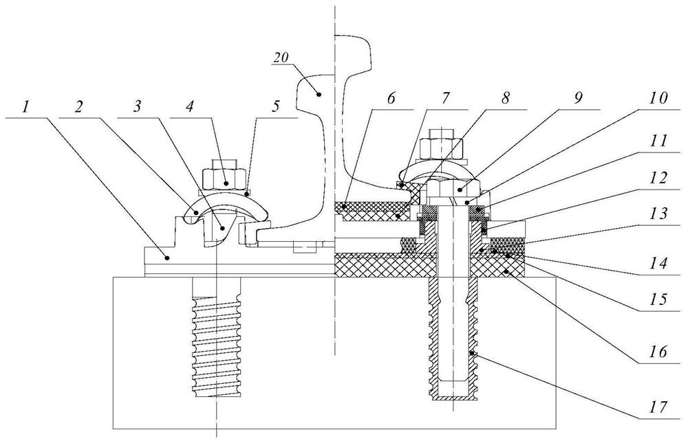
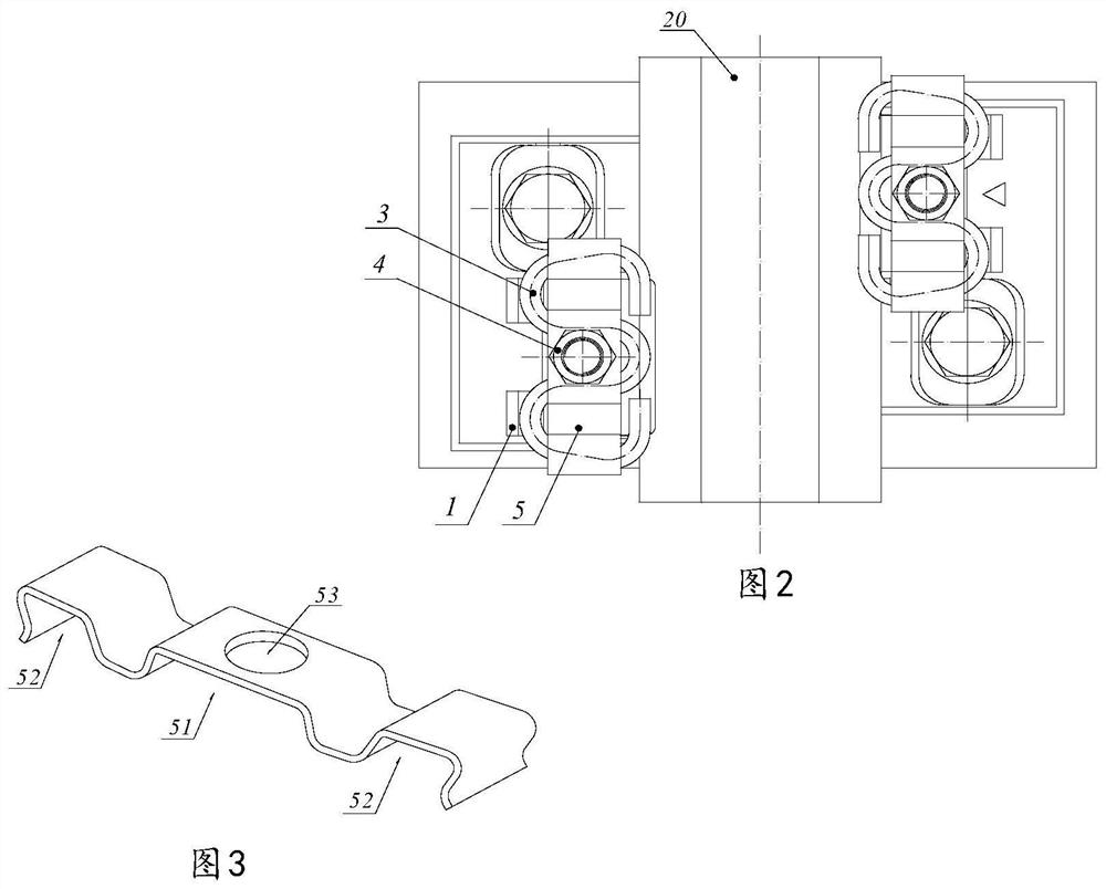
[0029] refer to figure 1 , figure 2 , a new type of bolted fastener for urban rail transit of the present invention includes an iron backing plate 1, an elastic strip 2, an elastic backing plate 6 under the rail, a T-shaped bolt 3, a lock nut 4, and a special-shaped anti-flying flat washer 5 and insulation gauge block 7. The iron backing plate 1 is installed and fixed on the under-rail foundation by anchor bolts 9, the under-rail elastic backing plate 6 is arranged under the bottom surface of the iron backing plate 1, and the steel rail 20 is located on the iron backing plate 1. The rail 20, the elastic backing plate 6 under the rail, the elastic strip 2, and the iron backing plate 1 can be regarded as the overall structure and vibrate synchronously. The vibration amplitude of the rail and the elastic strip is low, the deformation is small, and the d...


PUM


Abstract

A novel bolted fastener for urban rail transit is used for effectively reducing the overturning of a steel rail and the dynamic stress of an elastic strip, improving the stability of the steel rail and greatly prolonging the fatigue service life of the elastic strip. The novel bolted fastener comprises an iron backing plate, an elastic strip, an under-rail elastic backing plate, a T-shaped bolt, alocknut, a special-shaped flying-preventing flat washer and insulating damping track gauge blocks, the iron base plate is fixedly installed on the under-rail foundation through anchor bolts, an under-plate elastic base plate is arranged below the bottom face of the iron base plate, and the steel rail is located on the iron base plate. The insulating damping track gauge blocks are located on the top face and the outer side of the steel rail bottom. The lower end of the T-shaped bolt is installed on the iron base plate, the upper portion of the T-shaped bolt is sleeved with the special-shaped anti-flying flat washer and the locknut to press the elastic strip, the front end of the elastic strip acts on the top face of the insulation damping gauge block, and the rear end of the elastic stripacts on an iron base plate boss.

Description

technical field [0001] The invention relates to rail traffic, in particular to a novel fastener with bolts for urban rail traffic. Background technique [0002] Rail fasteners are the main part of the track structure and an important part that connects the rail and the foundation under the rail. The main functions of fasteners include: (1) maintaining and adjusting the gauge and direction of the rail; (2) providing longitudinal resistance to prevent the rail from crawling and breaking the rail from being too large; (3) providing elasticity to reduce vibration and impact; (4) Increase the rigidity of the track frame to prevent the track from buckling; (5) Provide track insulation to ensure the normal operation of the track circuit; (6) Have a certain ability to adjust the height of the rail. [0003] According to the classification of the clip fixing method, the commonly used fasteners in domestic rail transit can be divided into bolt fasteners and boltless fasteners. Faste...

Claims


Application Information

Patent Timeline
Patent Type & Authority Applications(China)
IPC IPC(8): E01B9/62E01B9/68E01B19/00
CPCE01B9/62E01B9/68E01B19/003
Inventor 辛杰周华龙刘锦辉周昌盛宋剑伟钟文文龙宏德朱颖周勇柯铁峰陈罄超周明亮刘启峰苟波王小韬李伟刘德志刘继辉郑晓练
Owner CHINA RAILWAY ERYUAN ENG GRP CO LTD
Why Eureka
Try Eureka