Electromechanical cylinder for lock

a technology of electronic or electromechanical cylinders and locks, which is applied in the field of electromechanical cylinders for locks, can solve the problems of inability to use, complexity of its manufacture and installation, and inability to fit electronic or electromechanical double knob cylinders of the type described abov

Inactive Publication Date: 2010-01-21
SALTO SYST SL
View PDF19 Cites 43 Cited by
  • Summary
  • Abstract
  • Description
  • Claims
  • Application Information

AI Technical Summary

Benefits of technology

[0016]The electronic module of the cylinder is fixed to the body of the cylinder by means of introducing the rotor into a housing made for the purpose in that cylinder body, in such a wa...

Problems solved by technology

Nevertheless, the double knob design in cylinders displays the drawback that they cannot be used in locks that have an arrangement such that prevents the cylinder from traversing from one side to the other, corresponding in this case to American, Australian and Scandinavian mortise locks in which half cylinders are used, one on the outside and the other on the inside, and whose bodies or half cylinders do not traverse the lock from one side to the other.
So, in this type of lock the outside cannot be connected with the inside of the cylinder, therefore electronic or electromechanical double knob cylinders of the type described above cannot be fitted.
Another disadvantage of the type of cylinder that we are referring to is the complexity of its manufacture and installation owing to the need to electrically interconnect the reader for the outer knob with the inner knob, in which this electrical connection means that all the parts of the cylinder have to be fitted from the factory on a cylinder body with a length that is already determined.
Moreover, the actuator element of the cylinder for actuating the lat...

Method used


Image

  • Electromechanical cylinder for lock
  • Electromechanical cylinder for lock
  • Electromechanical cylinder for lock

Examples


Embodiment Construction

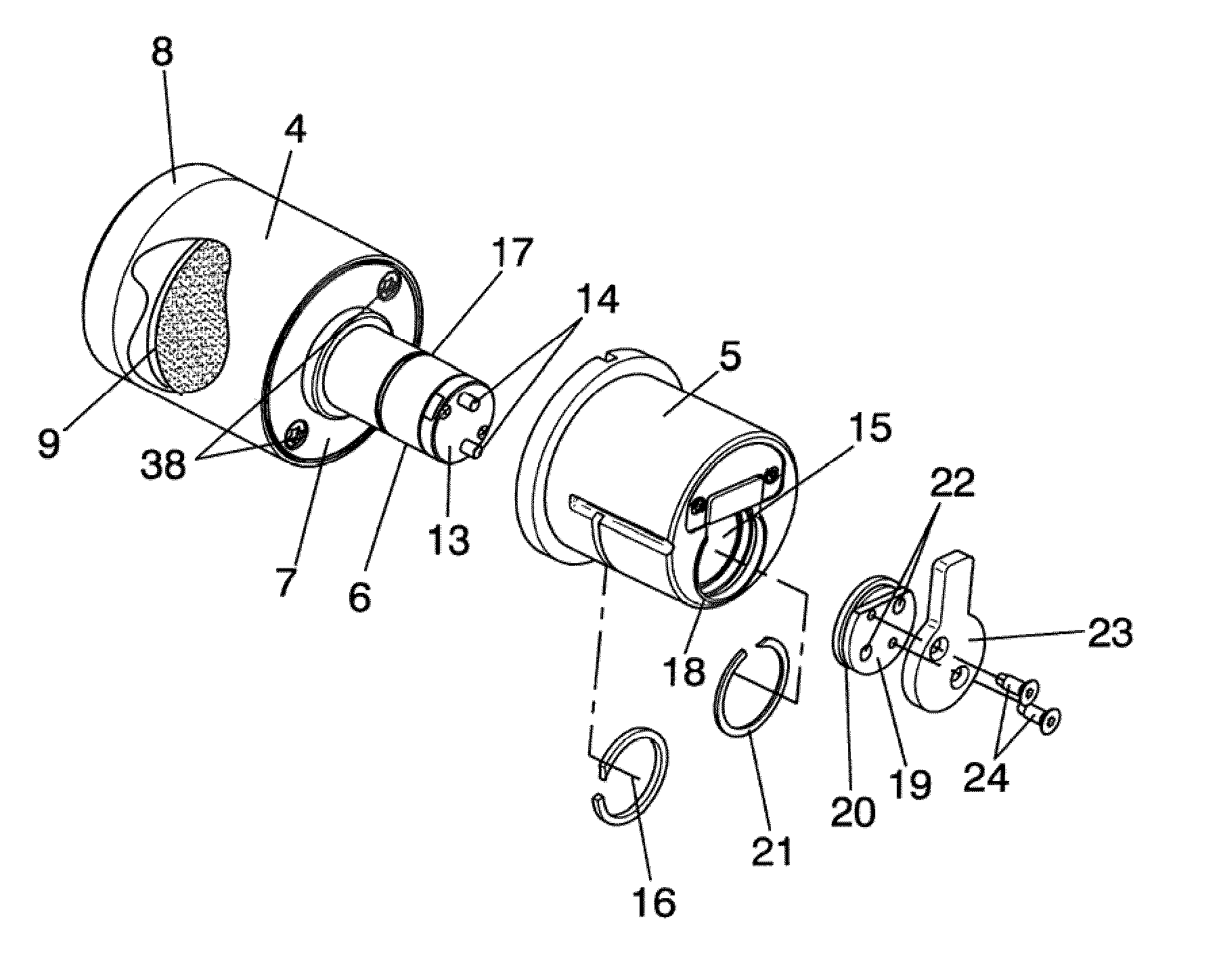
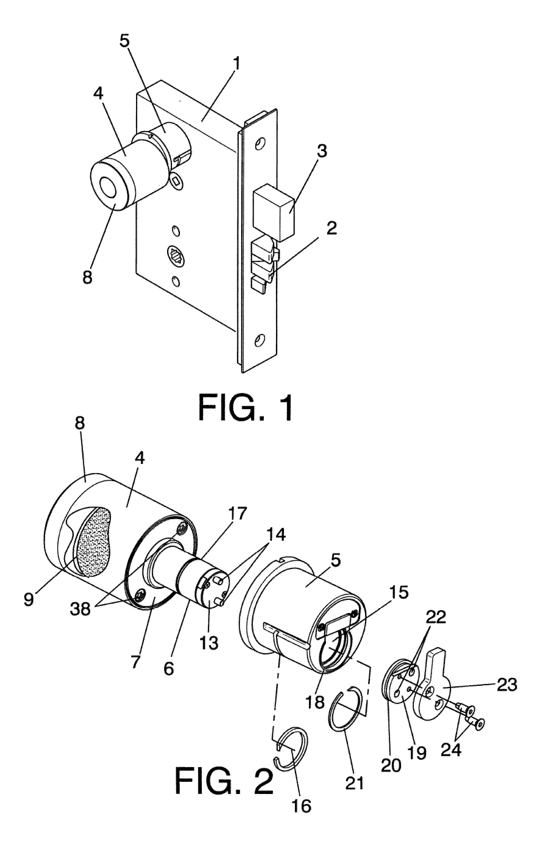
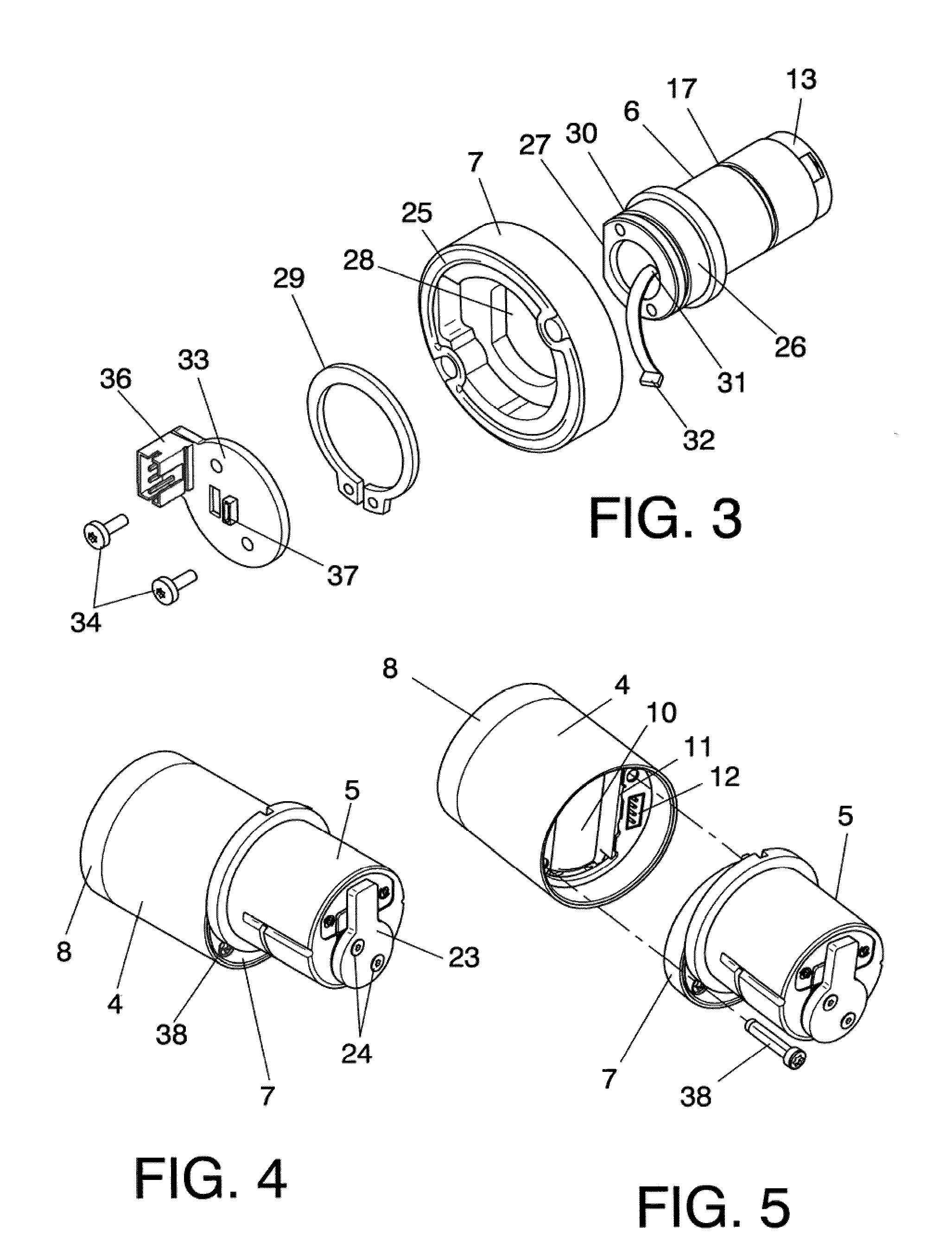
[0013]The electromechanical cylinder for locks forming the object of the invention presents a series of innovations that permit the problems raised above to be solved, achieving great security in it.

[0014]In that regard, the inventive cylinder comprises a mechanical cylinder body which is what is fitted in the corresponding lock and an electronic module that can be coupled externally to the mechanical body of the cylinder, in which this electronic module in turn comprises a knob and a rotor.

[0015]In terms of the knob, this includes on its inside an external reader cover, a control circuit and some electrical supply batteries, while the rotor includes a drive motor and a clutch mechanism.

[0016]The electronic module of the cylinder is fixed to the body of the cylinder by means of introducing the rotor into a housing made for the purpose in that cylinder body, in such a way that in that assembly the electronic module with the rotor is able to turn freely with respect to the body of the...


PUM


Abstract

The electromechanical cylinder is of the kind consisting of a knob (4) fixed to the cylinder body (5) fitted in the respective lock, in correspondence with the outer face of the latter, in other words it includes a single knob, with the particular feature that the rotor (6) which, together with the knob (4), form an electronic module, is located in a housing (15) of the cylinder body (5) and is retained therein axially but with the possibility of rotating freely, in such a way that in fitting the rotor (6) on the knob (4) the former remains in the inner and inaccessible part in order to prevent any manipulation thereof, this being a consequence of the fact that a base (7) forming the fastening element between the knob (4) and the cylinder body (5) is fixed by means of screws (38) which, in the assembly of the unit, remain facing in proximity to the actual door in which the lock is located, preventing such possible manipulations or violent acts.

Description

OBJECT OF THE INVENTION[0001]As stated in the title of this descriptive specification, the present invention relates to an electromechanical cylinder for lock, intended for its application in virtually all mortise locks, replacing the mechanical cylinders, the cylinder furthermore being of the kind that includes just one knob.[0002]The aim of the invention is to provide a cylinder for a lock with a single knob and which is applicable to the different types of lock to mortise, whether they be of the kind that use through cylinders, as in the case of European ones, or those that use half cylinders as in the case of American, Scandinavian and Australian locks. As well as the cylinder being valid with any kind of lock mentioned above, it also provides greater security against possible fraudulent manipulations or vandalism compared to conventional ones.BACKGROUND OF THE INVENTION[0003]In the lock-making sector there exist locks that incorporate cylinders with two knobs, one on the inside...

Claims


Application Information

Patent Timeline
IPC IPC(8): E05B49/02
CPCE05B47/0012E05B47/0615E05B47/068E05B2047/0058E05B63/08E05B2047/0017E05B2047/0026E05B63/0056Y10T70/7102E05B47/0676
Inventor IMEDIO OCANA, JUAN
Owner SALTO SYST SL
Why Eureka
Try Eureka