Shock absorbing member

a technology of shock absorption member and shock absorber, which is applied in the direction of bumpers, vehicle components, vehicular safety arrangments, etc., can solve the problems of unsuitable methods for shock absorption members, achieve the effect of reducing the stress applied to each of the flange portions, facilitating the bending of the vertical ribs at the application of impact thereto, and facilitating buckling distortion of the shock absorption member under constant load

Inactive Publication Date: 2010-01-21
INOAC CORP +1
View PDF63 Cites 6 Cited by
  • Summary
  • Abstract
  • Description
  • Claims
  • Application Information

AI Technical Summary

Benefits of technology

[0012]According to the first aspect of the invention, when the pressure receiving wall portion is pressed by the impact, the side wall portion formed on one end portion side of the pressure receiving wall portion is deformed in a direction intersecting with the side wall portion, i.e., a direction intersecting with the longitudinal direction of the pressure receiving wall portion. Thus, stress acting in a direction intersecting with the longitudinal direction of the pressure receiving wall portion is applied to the flange portion provided on one end portion side of the side wall portion. On the other hand, the vertical ribs formed on the opposite side of the pressure receiving wall portion are deformed in a direction intersecting with the vertical ribs, i.e., the longitudinal direction of the pressure receiving wall portion. In addition, stress acting along the longitudinal direction of the pressure receiving wall portion is applied to the flange portion corresponding to the end portion side of each of the vertical ribs. Thus, the shock absorbing member according to the invention is such that when the pressure receiving wall portion is pressed by the impact, stress acting in each of directions intersecting with each other is generated. Consequently, the stress generated at the application of impact thereto can be dispersed. In addition, the stress applied to each of both the flange portions can be reduced.
[0013]According to the second aspect of the invention, the bending groove is formed in the surface of each of the vertical ribs, which intersects with the longitudinal direction. Thus, the bending of the vertical ribs at the application of impact thereto is facilitated. Consequently, the vertical ribs can surely be bent in the longitudinal direction of the pressure receiving wall portion.
[0014]According to the third aspect of the invention, the thickness of the side wall portion is reduced towards one end portion side thereof corresponding to the flange portion from the other end portion side thereof corresponding to the pressure receiving wall portion. Thus, the flange portions serving as attaching portions can be prevented from being broken. In addition, the buckling distortion of the shock absorbing member under a constant load can be facilitated. Consequently, a shock load can be reduced to a low level.

Problems solved by technology

Therefore, this method is not suitable for the shock absorbing member 70.

Method used


Image

  • Shock absorbing member
  • Shock absorbing member
  • Shock absorbing member

Examples


Embodiment Construction

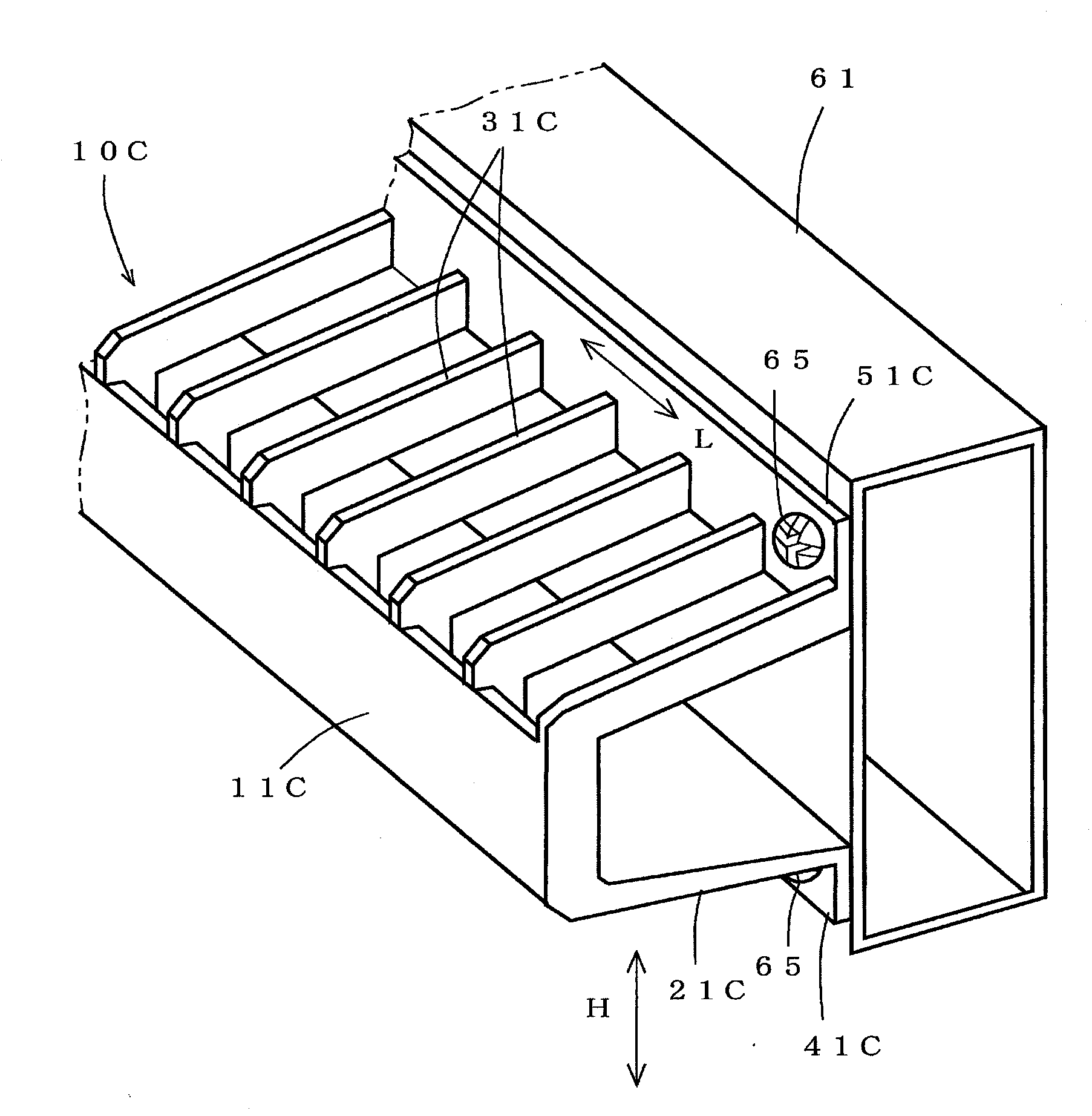
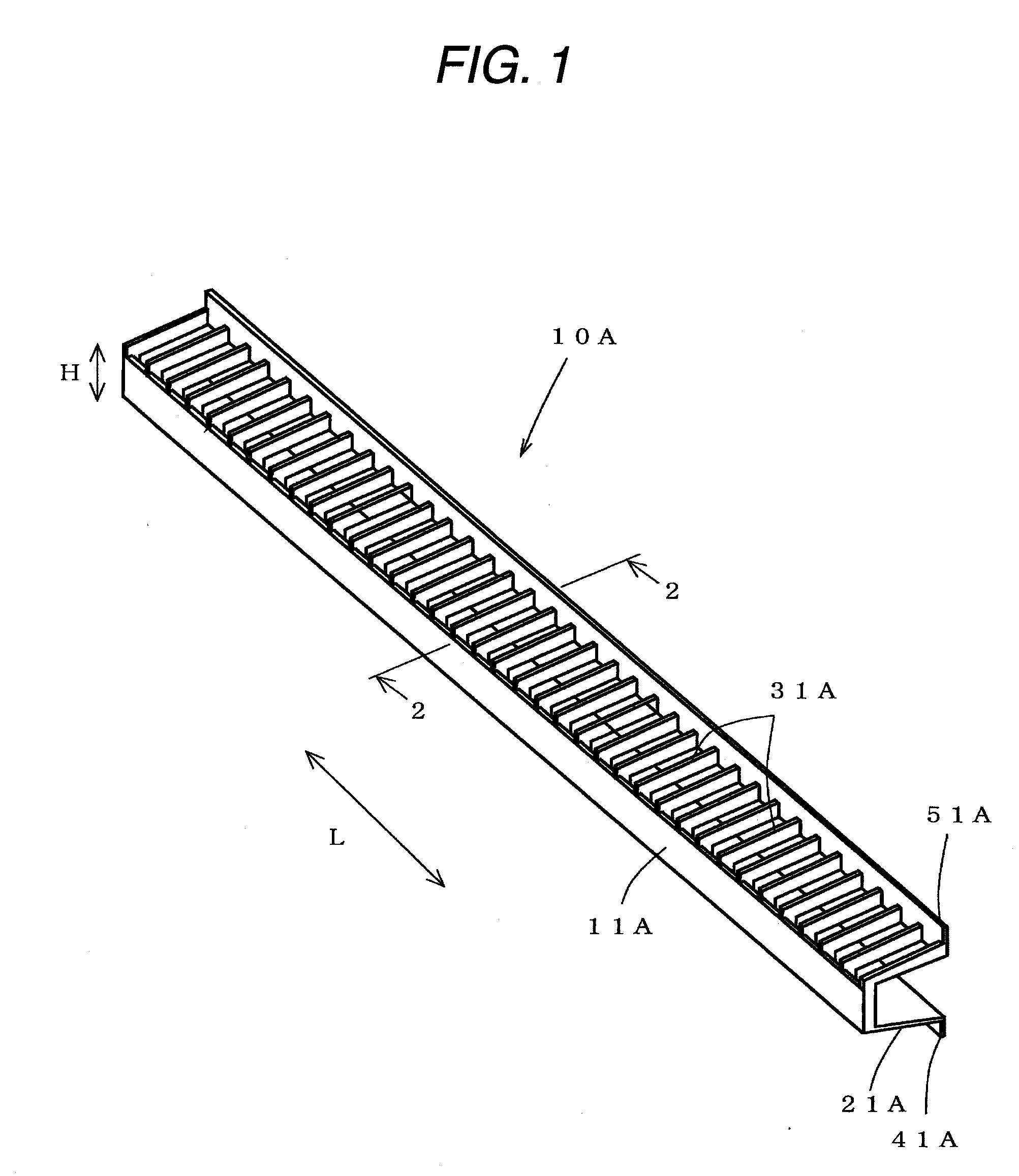
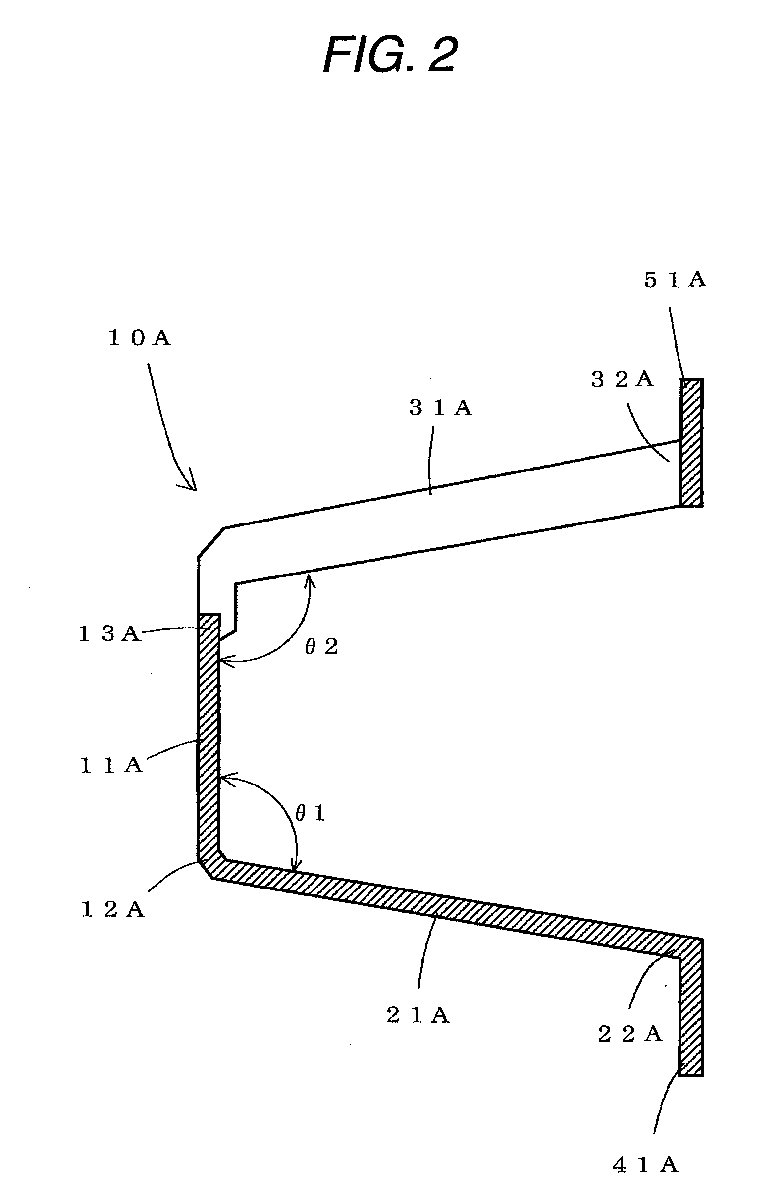
[0032]Hereinafter, exemplary embodiments of the invention are described in detail. FIG. 1 is a perspective view illustrating a shock absorbing member according to a first embodiment of the invention. FIG. 2 is a cross-sectional view taken on line 2-2 illustrated in FIG. 1. FIG. 3 is a perspective view illustrating an attached state of the shock absorbing member according to the first embodiment. FIG. 4 is a perspective view illustrating a shock absorbing member according to a second embodiment of the invention. FIG. 5 is a cross-sectional view taken on line 5-5 illustrated in FIG. 4. FIG. 6 is a perspective view illustrating an attached state of the shock absorbing member according to the second embodiment. FIG. 7 is a perspective view illustrating a shock absorbing member according to a third embodiment of the invention. FIG. 8 is a cross-sectional view taken on line 8-8 illustrated in FIG. 7. FIG. 9 is a perspective view illustrating an attached state of the shock absorbing member...


PUM


Abstract

An object of the invention is to provide a shock absorbing member enabled to reduce stress applied at the moment of impact to each part serving as an attaching portion. The shock absorbing member 10A includes a pressure receiving wall portion 11A to be pressed at the moment of impact, a side wall portion 21A formed on one end portion side in a direction H perpendicular to a longitudinal direction L of the pressure receiving wall portion 11A to extend along the longitudinal direction L towards a rear of the pressure receiving wall portion 11A, a plurality of vertical ribs 31A that are formed on the other end portion side of the pressure receiving wall portion 11A opposite to the one end portion side, on which the side wall portion 21A is formed, that are provided towards the rear of said pressure receiving wall portion 11A to intersect with the longitudinal direction L, that are arranged like rows to the longitudinal direction L, and flange portions 41A and 51A respectively formed on one end portion side of the side wall portion 21A, which is opposite to the pressure receiving wall portion 11A, and on one end portion side of each of the vertical ribs 31A, which is opposite to the pressure receiving wall portion 11A.

Description

TECHNICAL FIELD[0001]The present disclosure relates to a shock absorbing member suitable as a component member of a bumper or the like of an automobile.BACKGROUND ART[0002]There has been a synthetic resin shock absorbing member 70 including a pressure receiving wall portion 71 and side wall portions 73, 73, as illustrated in FIG. 11. The synthetic resin shock absorbing member 70 is used as the shock absorbing member of a bumper of an automobile and is formed by being transverse-cross-sectionally substantially U-shaped. Each of the side wall portions 73, 73 of the synthetic resin shock absorbing member 70 is formed to extend from an associated one of both end portions 72, 72 of the pressure receiving wall portion 71 placed in a direction (i.e., an up-down direction of a vehicle) H1 intersecting with a longitudinal direction (i.e., a direction perpendicular to the drawing in the case of an example illustrated therein) towards the rear of the pressure receiving wall portion 71 along th...

Claims


Application Information

Patent Timeline
Patent Type & Authority Applications(United States)
IPC IPC(8): B60R19/26
CPCB60R2019/1893B60R19/18
Inventor SUZUKI, HIROAKITOYOGUCHI, YASUHIROMITSUYAMA, SOSHI
Owner INOAC CORP
Why Eureka
Try Eureka