
Visualisation System in an Aircraft

a visualisation system and aircraft technology, applied in the field of aircraft visualisation system, can solve the problems of inability to offer passengers the full experience of a program or feature film, frequent long-distance flights over several hours, and high cos

Inactive Publication Date: 2010-01-21
AIRBUS OPERATIONS GMBH
View PDF19 Cites 37 Cited by
  • Summary
  • Abstract
  • Description
  • Claims
  • Application Information

AI Technical Summary

Benefits of technology

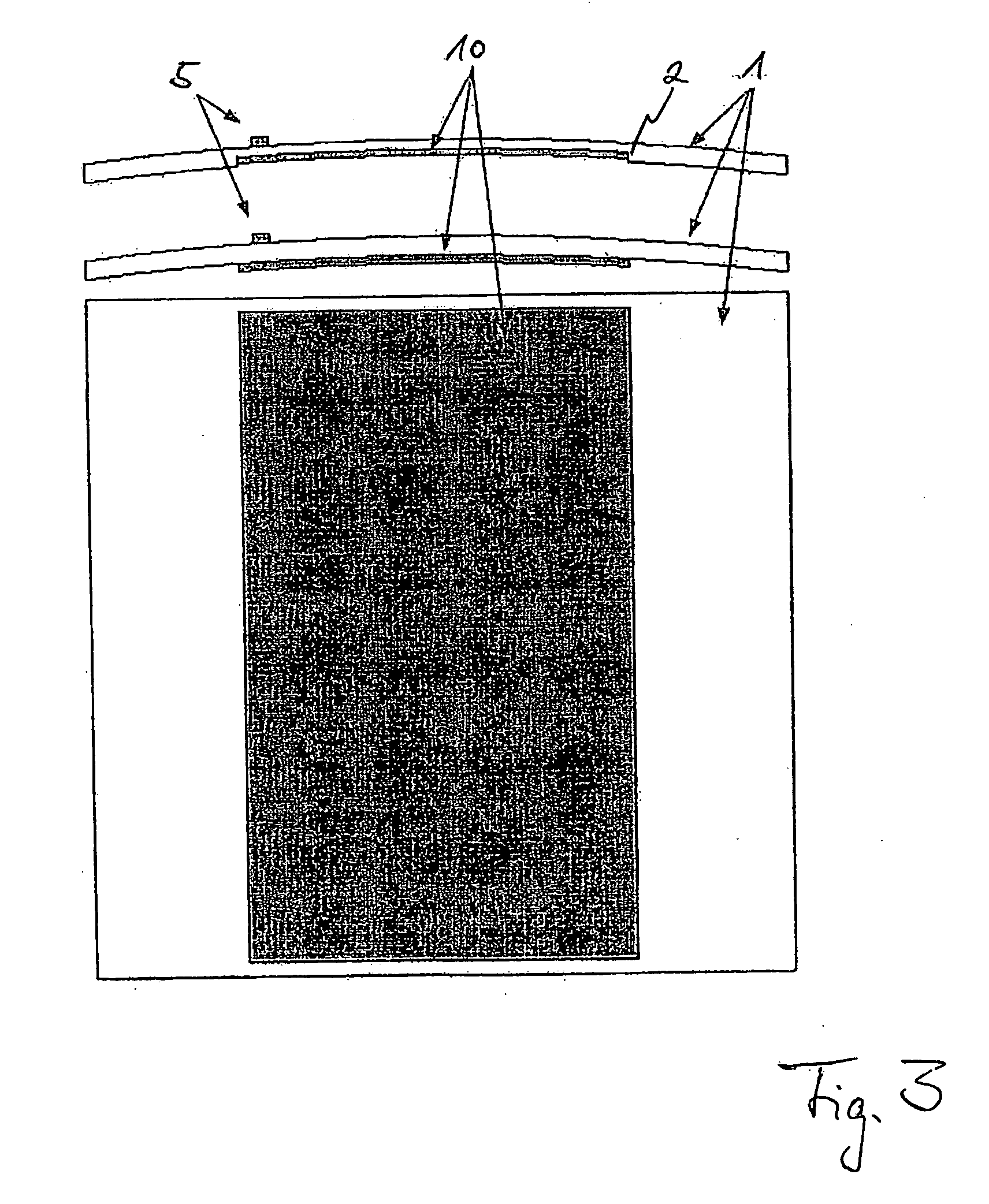
[0012]Instead of coating the outside of the lining panel with the display, it is of course also possible to create an area-shaped recess on the surface of the lining panel and to embed the flexible display in said area-shaped recess. While the above-mentioned OLED displays are as a rule very flat, such a design in which the display is embedded in the surface of the lining panel makes it possible to create an even surface without any uneven areas worth mentioning.
[0013]In the case of organic light emitting diodes (hereinafter referred to as OLEDs), these can be light emitting diodes made of organic semiconducting polymers or small molecules that can be produced far more economically than inorganic LEDs. By arranging a multitude of small OLEDs it is, for example, possible to create a graphic display as proposed for use in the context of the present invention. As an alternative, the OLEDs applied to the lining panel can also be used for illumination purposes, for example in order to create particular illumination scenarios in the aircraft cabin. Since a display constructed in this way with the use of OLEDs, in contrast to conventional liquid-crystal display monitors, does not need background illumination, the display can be designed so as to be translucent, which in the context of the present invention is desirable so as not to negatively affect the surface characteristics of the lining panel. Apart from this, the fact that no background illumination is needed has a positive effect on the weight of the display so that considerable weight can be saved when compared to conventional liquid-crystal display monitors.
[0024]Since sooner or later aircraft manufacturers will produce blended wingbody aircraft that will no longer have any windows but instead a far wider cabin, the effect of artificially created windows, window strips and any imaginable window shapes is particularly interesting because otherwise the passenger gains the impression of being seated in a completely closed space, which in flight can lead to a state of anxiety. In order to counteract this, by means of the invention, the interior linings of the passenger cabin can be coated with flexible displays on which the view from the cabin is artificially simulated so that a passenger gains the impression of actually looking out of a window.
[0025]By arranging the translucent flexible displays preferably on the cabin ceiling panels, a positive effect can be achieved in that passengers can enjoy the graphic effects, for example of a feature film shown on the displays, while lying down, which can contribute to the best possible passenger relaxation.

Problems solved by technology

Long-distance flights over several hours can frequently be lengthy and monotonous, which is why in older types of large-capacity passenger aircraft only a few monitors or flat-panel monitors are arranged, distributed in the cabin, for entertaining, instructing and informing passengers.
However, these monitors are often arranged such that only a few passengers have an unrestricted view of the monitors.
However, these monitors are associated with considerable weight, which is of course always undesirable in the field of aircraft and space technology.
Moreover, both the monitors arranged so as to be distributed in the cabin, and the flat-panel monitors arranged in the backrests are associated with disadvantages in that they are very small, and thus due to their size cannot offer passengers the full experience of a program or feature film when viewed on these monitors.

Method used


Image

  • Visualisation System in an Aircraft
  • Visualisation System in an Aircraft
  • Visualisation System in an Aircraft

Examples


Embodiment Construction

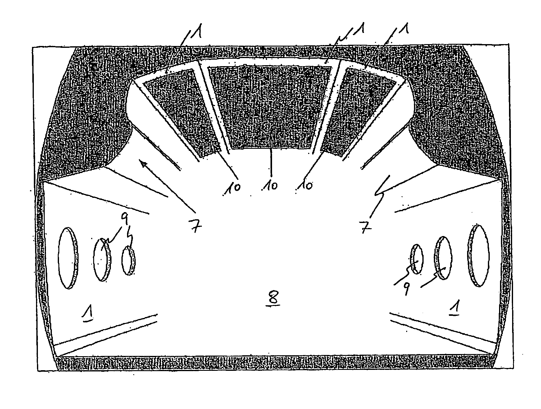
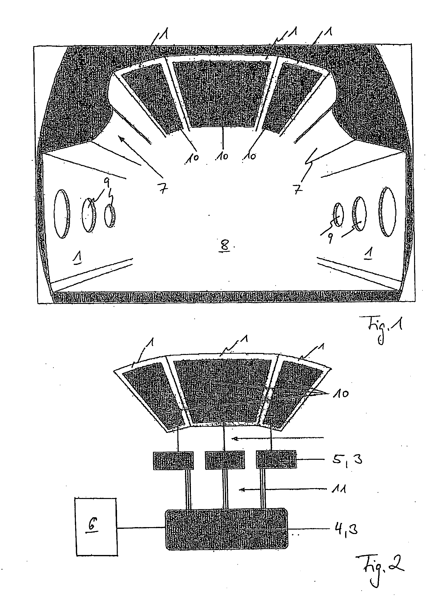
[0031]FIG. 1 shows a view of the interior of a passenger cabin 8. The passenger cabin 8 is shown diagrammatically without any interior equipment components such as, for example, seats. The passenger cabin 8 is laterally delimited by lining panels 1 in which aircraft windows 9 are fitted at regular spacing. Towards the top the passenger cabin 8 is delimited by a cabin ceiling in the form of three fitting panels 1 that abut against each other at their front faces. In the transition region between the lateral linings 1 and the cabin ceiling there are hatracks 7, which for the purpose of these explanations are shown diagrammatically only.

[0032]As shown in FIG. 1, in the region of the cabin ceiling the lining panels 1 comprise translucent flexible displays 10 on which various visual effects or for example entertainment media can be played, as will be explained below with reference to the additional figures. Due to their flexibility the displays 10 can easily be made to match the concave ...


PUM


Abstract

A visualization system in the passenger cabin of an aircraft, by which visualization system data relating to informing, instructing and entertaining passengers can be visually presented, along with graphic effects. The visualization system includes a lining panel to line the passenger cabin, and a control unit. The lining panel is coated with a flexible display that is coupled to the control unit, which, for the purpose of presenting information, is equipped to supply electricity in a targeted manner to the display.

Description

REFERENCE TO RELATED APPLICATIONS[0001]This application claims the benefit of the filing date of German Patent Application No. 10 2006 007 285.5 filed Feb. 16, 2006 and of U.S. Provisional Patent Application No. 60 / 774,154 filed Feb. 16, 2006, the disclosure of which applications is hereby incorporated herein by reference.TECHNICAL FIELD[0002]The present invention generally relates to the technical field of equipment installation in an aircraft. In particular, the invention relates to a visualisation system in the passenger cabin of an aircraft, by means of which visualisation system data relating to informing, instructing and entertaining passengers can be visually presented, as can graphic effects. Furthermore, the invention relates to an aircraft equipped with a visualisation system according to the invention.BACKGROUND TO THE INVENTION[0003]Long-distance flights over several hours can frequently be lengthy and monotonous, which is why in older types of large-capacity passenger a...

Claims


Application Information

Patent Timeline
IPC IPC(8): H04N5/64B64D11/00
CPCB64D11/0015B64D2011/0061Y02T50/46G09F9/33G09G3/3208G06F3/1438Y02T50/40B64D11/00153
Inventor STAVAEUS, MIKAELWISCH, BODOSUSS, WOLFGANGROWOLD, LARS
Owner AIRBUS OPERATIONS GMBH
Learn More