
Landmark information system for an aircraft

a technology for aircraft and information systems, applied in television systems, navigation instruments, instruments, etc., can solve the problems of limiting the quantity of information to be presented, the field of view of a viewer looking at the landscape from the aircraft window may be limited, etc., to achieve the effect of expanding the visual environment of the passenger and certain individuality

Active Publication Date: 2008-01-24
AIRBUS OPERATIONS GMBH
View PDF23 Cites 28 Cited by
  • Summary
  • Abstract
  • Description
  • Claims
  • Application Information

AI Technical Summary

Benefits of technology

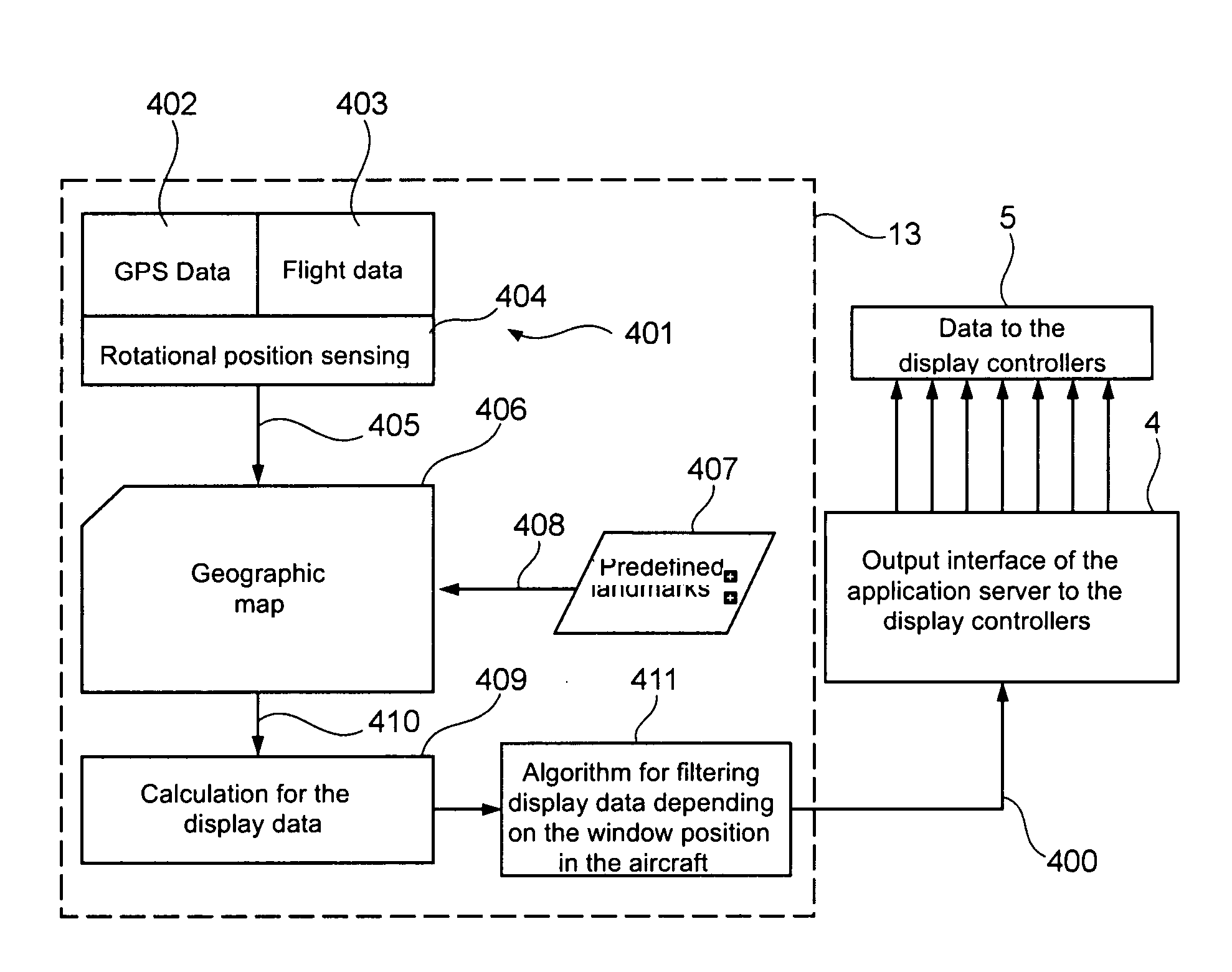
[0011] The position of the aircraft may, for example, be compared with information contained in a (3-D) terrain database. In this way it is possible to determine which landmarks are in (direct) proximity or which landmarks are of particular interest so as to be presented on a display.
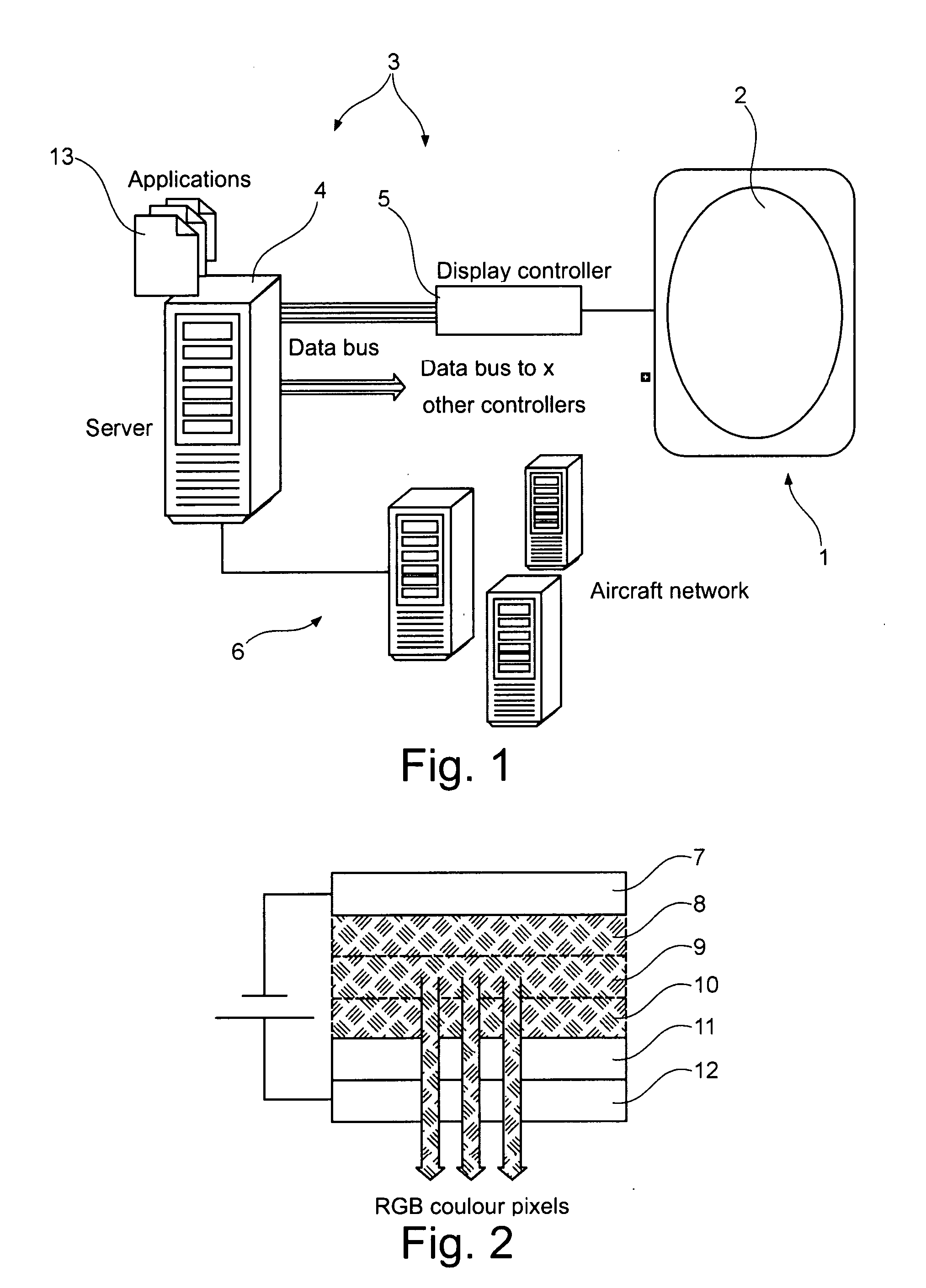
[0022] In the case of organic light emitting diodes (hereinafter referred to as OLEDs), these may be light emitting diodes made of organic semiconducting polymers or small molecules that may be produced far more economically than inorganic LEDs. By arranging a multitude of small OLEDs it is, for example, possible to create a graphic display as proposed for use in the context of the present invention. As an alternative, the OLEDs applied to the pane of the aircraft window may also be used for illumination purposes, for example in order to create particular illumination scenarios. Since a display constructed in this way with the use of OLEDs, in contrast to conventional liquid-crystal display monitors, does not need background illumination, the display may be designed so as to be translucent, which in the context of the present invention is necessary so as not to impede the unrestricted view through the aircraft window. Apart from this, the fact that no background illumination is needed has a positive effect on the weight of the display so that considerable weight may be saved when compared to conventional liquid-crystal display monitors.
[0025] Flight data may be communicated to the flight data determination device by way of the instruments of the aircraft. Since the position and situation of landmarks is to be determined it may be advantageous if information about the flight route at the time is known. It is thus possible to determine the position of the aircraft or of some other means of locomotion on land or sea.
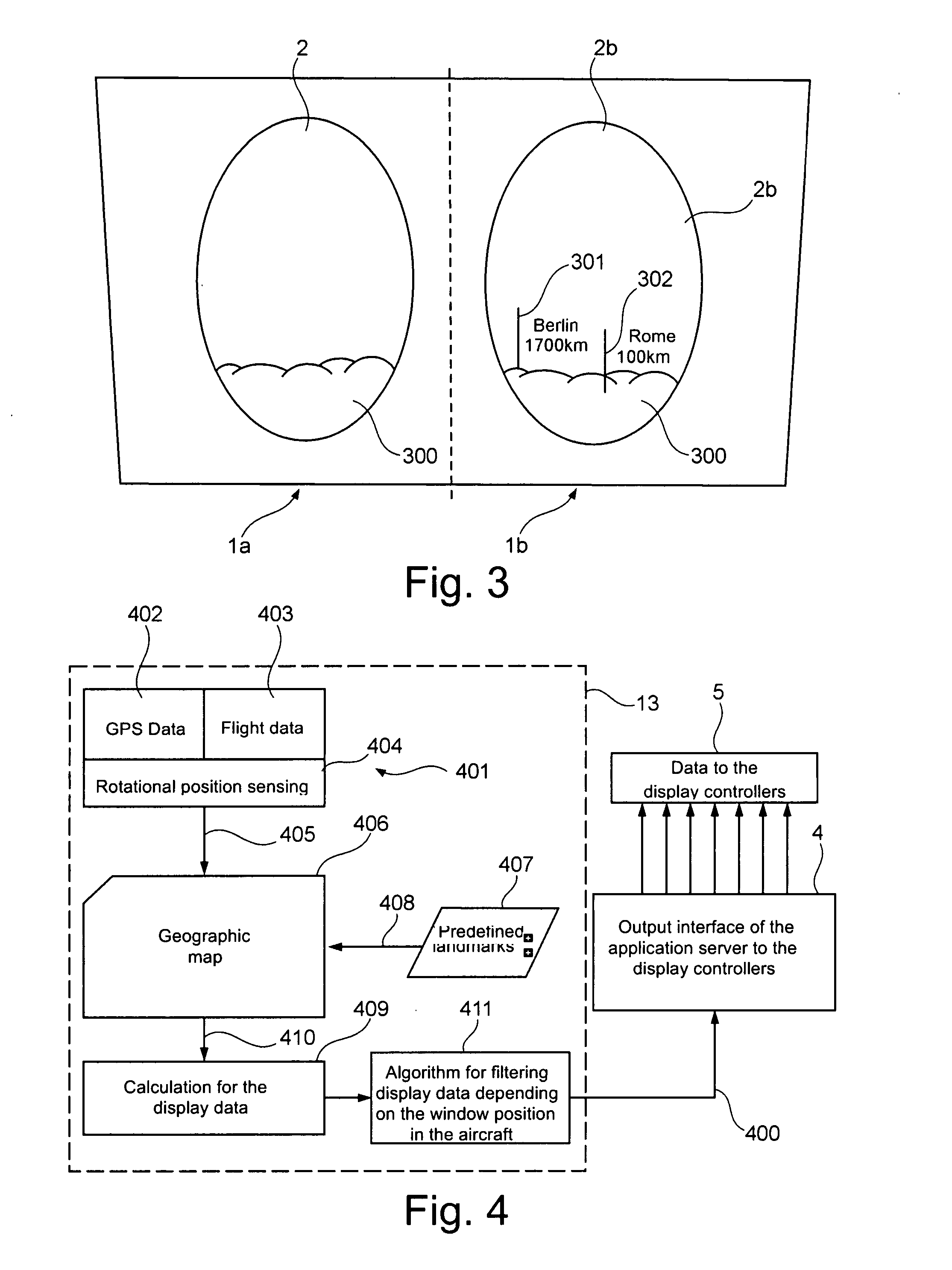
[0041] When all the additional information has been determined, displaying it may take place directly on the aircraft window. In this way a relationship between the additional geographic data and the field of view of the passenger, which field of view is currently present at the time the passenger looks out of the window, may be established. In this way the passenger may quickly access the desired information in a manner that is close to reality. To this effect the information determined by the landmark determination device may be displayed on the aircraft window by way of a translucent display.
[0047] The present invention may be used to visually present geographic data that is incorporated in the real field of view of the passenger. A landmark information system may be an add-on to the onboard entertainment system. In this way a new information channel may be opened up, and an airline may well gain a competitive advantage and a certain individuality.
[0049] A landmark information system may be regarded as a new and fascinating entertainment add-on, and may help an airline gain a competitive advantage and more individuality. In combination with conventional seat monitors and ceiling monitors, parallel operation of various emissions such as flight information and cinema may take place. Energy savings may be achieved when compared to conventional seat monitors and ceiling monitors. Moreover, OLED displays may be used, which feature lower power consumption than is the case with LCD displays.

Problems solved by technology

Through the aircraft window the field of view of a viewer looking at the landscape from the aircraft window may be limited.
The landmarks that a viewer currently sees when looking through the aircraft window may therefore limit the quantity of information to be presented.

Method used


Image

  • Landmark information system for an aircraft
  • Landmark information system for an aircraft
  • Landmark information system for an aircraft

Examples


Embodiment Construction

[0063]FIG. 1 shows a system overview of the landmark information system according to the invention. As shown in FIG. 1, the landmark information system according to the invention comprises at least one aircraft window 1 to which at least one windowpane 2 has been fitted. Furthermore, the landmark information system also comprises a control unit 3, which may, for example, comprise a server computer 4 with a multitude of display controllers 5. In order to visually display certain information or entertainment media on the windowpane, the pane 2 of the aircraft window 1 is coated with a translucent display. This coating may, for example, be implemented by direct coating of the pane 2 with a multitude of organic light emitting diodes. As an alternative, the coating may be implemented by a film on which OLEDS are arranged in columns and rows.

[0064] As further shown in FIG. 1, the translucent display of the aircraft window 1 is coupled to the control unit 3 in order to be caused, by the c...


PUM


Abstract

A landmark information system in an aircraft, by which landmark information system data relating to informing, instructing and entertaining passengers may be visually presented. An aircraft equipped with a landmark information system is also provided. The landmark information system comprises an aircraft window with at least one pane and a control unit. The at least one pane is coated with a translucent display that is coupled to the control unit, which, for the purpose of presenting information, is equipped to supply electrical current in a targeted manner to the display. Furthermore, the landmark information system comprises a landmark determination device which may provide geographic data relating to landmarks, for presentation on the translucent display.

Description

CROSS-REFERENCE TO RELATED APPLICATIONS [0001] This application claims the benefit of the filing date of U.S. Provisional Patent Application No. 60 / 774,155 filed Feb. 16, 2006, the disclosure of which is hereby incorporated herein by reference.BACKGROUND OF THE INVENTION [0002] The present invention generally relates to the technical field of equipment installation in an aircraft. In particular, the invention relates to a landmark information system for an aircraft, by which landmark information system data relating to informing, instructing and entertaining passengers may be visually presented. Furthermore, the invention relates to an aircraft equipped with a landmark information system according to the invention, to a method for visually presenting geographic data, to a computer-readable medium, and to a program element. [0003] In older types of large-capacity passenger aircraft, in particular in economy class, it is common for only a few monitors or flat-panel monitors to be arra...

Claims


Application Information

Patent Timeline
IPC IPC(8): G01C21/00
CPCG08G5/0021G01C23/005
Inventor STAVAEUS, MIKAELPETER, JANSUESS, WOLFGANGROWOLD, LARS
Owner AIRBUS OPERATIONS GMBH
Learn More