
Assessing aircraft interference path loss employing discrete frequency stirring

a discrete frequency stirring and interference path technology, applied in the direction of transmission monitoring, line-transmission details, receiver monitoring, etc., can solve the problems of time-consuming, high cost of testing, and hundreds of hours of testing

Active Publication Date: 2010-01-21
THE BOEING CO
View PDF13 Cites 23 Cited by
  • Summary
  • Abstract
  • Description
  • Claims
  • Application Information

AI Technical Summary

Benefits of technology

[0009]In yet another advantageous embodiment, an apparatus comprises a set of receive antennas, a set of transmit antennas, and a radio frequency control system. The radio frequency control system is capable of transmitting a plurality of radio frequency signals that are stepped through a plurality of frequencies in a frequency range the set of transmit antennas from a plurality of locations within an interior of an aircraft; measuring received

Problems solved by technology

This type of process; however, is time consuming and may require hundreds of hours to perform the tests within guideline procedures.
This type of testing is expensive.

Method used


Image

  • Assessing aircraft interference path loss employing discrete frequency stirring
  • Assessing aircraft interference path loss employing discrete frequency stirring
  • Assessing aircraft interference path loss employing discrete frequency stirring

Examples


Embodiment Construction

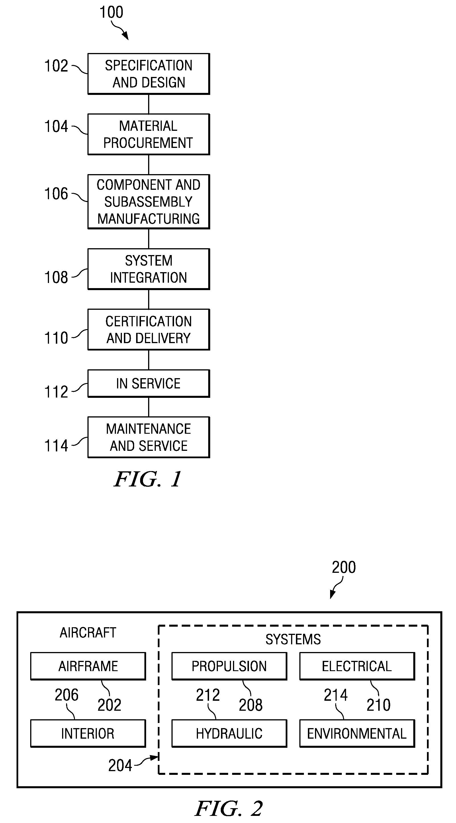
[0029]Referring more particularly to the drawings, embodiments of the disclosure may be described in the context of the aircraft manufacturing and service method 100 as shown in FIG. 1 and aircraft 200 as shown in FIG. 2. Turning first to FIG. 1, a diagram illustrating an aircraft manufacturing and service method is depicted in accordance with an advantageous embodiment. During pre-production, exemplary aircraft manufacturing and service method 100 may include specification and design 102 of aircraft 200 in FIG. 2 and material procurement 104. During production, component and subassembly manufacturing 106 and system integration 108 of aircraft 200 in FIG. 2 take place.

[0030]Thereafter, aircraft 200 in FIG. 2 may go through certification and delivery 110 in order to be placed in service 112. While in service by a customer, aircraft 200 in FIG. 2 is scheduled for routine maintenance and service 114, which may include modification, reconfiguration, refurbishment, and other maintenance ...


PUM


Abstract

A method for accessing aircraft interference path loss in an aircraft. A plurality of radio frequency signals that are stepped through a plurality of frequencies in a frequency range is transmitted from a plurality of locations within an interior of the aircraft. Radio frequency signals present at a receive antenna are received in response to transmitting the plurality of radio frequency signals to form a plurality of measurements. An average of averages curve is generated from the plurality of measurements. A peak to average ratio is identified. Field uniformity is identified. A standard error for the average of averages curve is determined. An upper bound for the aircraft interference path loss in the aircraft is predicted using the average of averages curve, the peak to average ration, the field uniformity, and the standard error.

Description

BACKGROUND INFORMATION[0001]1. Field[0002]The present disclosure relates generally to identifying interference path loss and in particular to a method and apparatus for identifying interference path loss associated with an aircraft. Still more particularly, the present disclosure relates to a method and apparatus for statistically identifying interference path loss associated with the transmission of radio frequency signals within an interior of an aircraft using discrete frequency stirring.[0003]2. Background[0004]In designing and manufacturing aircraft, reverberant environment measurement methods are used to identify the interference path loss of radio frequency signals from within an aircraft. The interference path loss is defined as the ratio of the radio frequency power at the aircraft communication, navigation or surveillance receiver input to the transmitted radio frequency power measured at the output of the transmitter connector at the reference antenna terminals. The ratio...

Claims


Application Information

Patent Timeline
IPC IPC(8): H04B17/00
CPCH04B7/18506H04B17/00H04B17/373H04B17/29H04B17/345H04B17/26
Inventor HORTON, NATHANIEL THOMASKIRCHOFF, KENNETH PATRICKLEWIS, DENNIS MICHAEL
Owner THE BOEING CO
Learn More