Method and system for quickly calibrating field uniformity of transient electromagnetic field

A technology of electromagnetic field and uniformity, applied in the direction of electromagnetic field characteristics, etc., can solve the problems of complex calibration process, long calibration time, slow calibration speed, etc., to achieve the effect of simple calibration process, short calibration time, and fast calibration speed.

Inactive Publication Date: 2012-12-19
BEIJING INST OF RADIO METROLOGY & MEASUREMENT
View PDF5 Cites 9 Cited by
  • Summary
  • Abstract
  • Description
  • Claims
  • Application Information

AI Technical Summary

Problems solved by technology

Therefore, the calibration method and system in the prior art have the problems of compl

Method used


Image

  • Method and system for quickly calibrating field uniformity of transient electromagnetic field
  • Method and system for quickly calibrating field uniformity of transient electromagnetic field
  • Method and system for quickly calibrating field uniformity of transient electromagnetic field

Examples


Embodiment 1

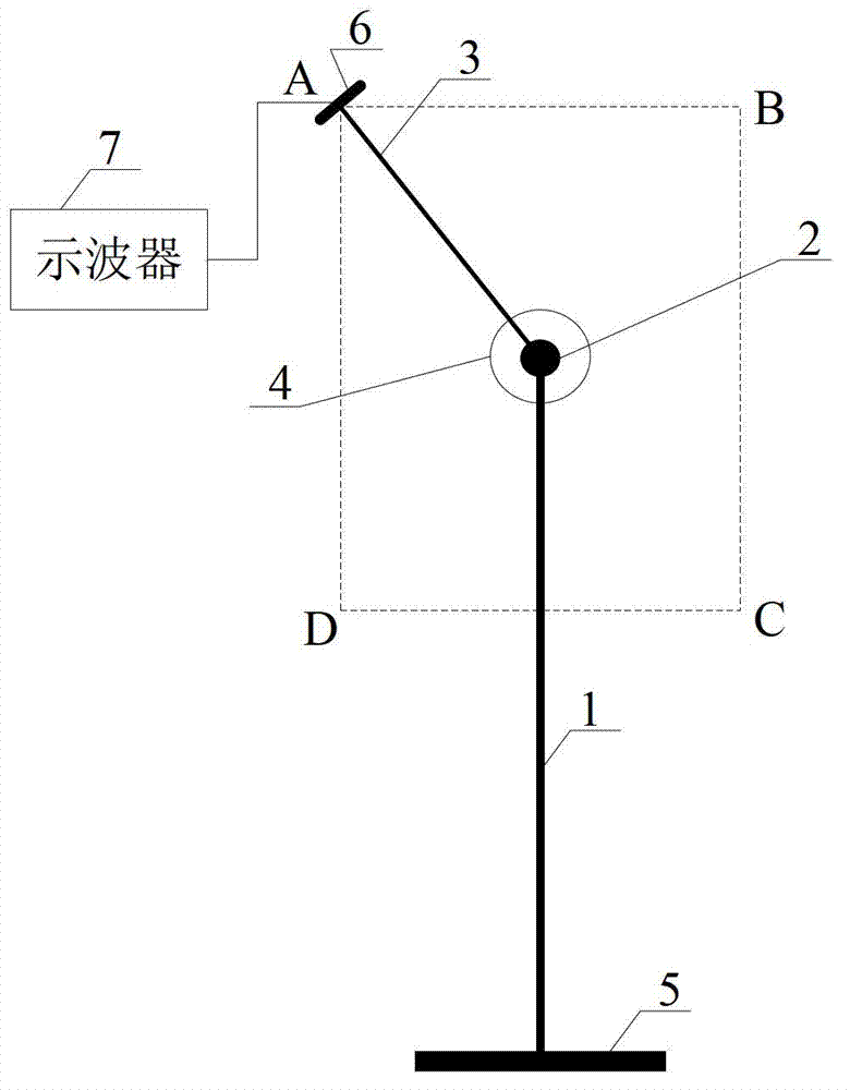
[0025] The system for quickly calibrating the uniformity of the transient electromagnetic field provided by this embodiment includes a support rod 1, a rotating shaft 2, a test rod 3, a positioning device 4, a base 5, a probe 6 and an oscilloscope 7, such as figure 1 shown. The rotating shaft 2 is arranged on the top of the support rod 1 . The bottom end of the support rod 1 is fixedly connected with the base 5 . In this embodiment, the height of the support rod 1 is adjustable, for example. One end of the test rod 3 is mounted on the rotating shaft 2 and can rotate around the rotating shaft 2 . The probe 6 is fixed on the free end of the test rod 3 , and the probe 6 is electrically connected with the oscilloscope 7 . A positioning device 4 is provided at the joint between the test rod 3 and the rotating shaft 2 . The positioning device 4 is used to limit the test rod 3 in a plane where the test rod 3 is located, and can fix the test rod 3 at any position. In this embodim...

Embodiment 2

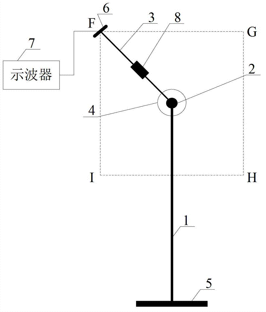
[0032] The system for quickly calibrating the uniformity of transient electromagnetic fields provided by this embodiment includes a support rod 1, a rotating shaft 2, a test rod 3, a positioning device 4, a base 5, a probe 6, an oscilloscope 7 and a length adjustment device 8, such as image 3 shown. The rotating shaft 2 is arranged on the top of the support rod 1 . The bottom end of the support rod 1 is fixedly connected with the base 5 . In this embodiment, the height of the support rod 1 is adjustable, for example. One end of the test rod 3 is mounted on the rotating shaft 2 and can rotate around the rotating shaft 2 . The probe 6 is fixed on the free end of the test rod 3 , and the probe 6 is electrically connected with the oscilloscope 7 . A positioning device 4 is provided at the joint between the test rod 3 and the rotating shaft 2 . The positioning device 4 is used to limit the test rod 3 in a plane where the test rod 3 is located, and can fix the test rod 3 at any...

Embodiment 3

[0039] This embodiment adopts the same system for quickly calibrating the uniformity of the transient electromagnetic field as in Embodiment 2.

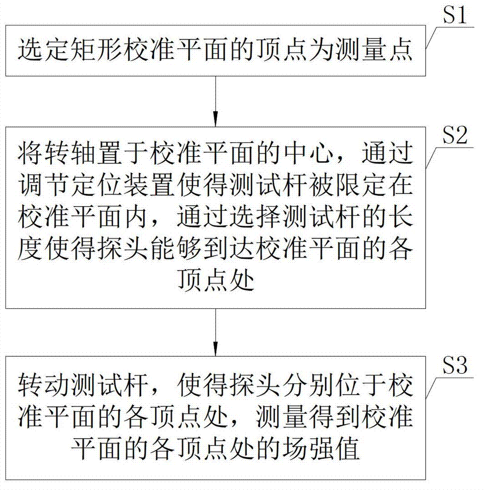
[0040] like Figure 4 As shown, select the first calibration plane JKLM of such as square, and adopt the calibration method described in embodiment 2 to obtain the field strength value E at J, K, L and M points for this calibration plane J ,E K ,E L and E M . A square second calibration plane NOPQ is selected, and the four vertices of the second calibration plane NOPQ are, for example, the midpoints of the sides of the first calibration plane JKLM respectively. For the second calibration plane NOPQ, adopt the calibration method described in embodiment 2 to obtain the field strength value E at the N, O, P and Q points N ,E O ,E P and E Q . The field strength value E that described method obtains J ,E K ,E L ,E M ,E N ,E O ,E P and E Q For the analysis and evaluation of the field uniformity of the transient electromagn...


PUM


Abstract

The invention discloses a method and a system for quickly calibrating field uniformity of transient electromagnetic field. The method includes the steps of selecting apexes of a rectangular calibrating plane as measuring points; placing a rotary shaft (2) at the center of the calibrating plane, adjusting a positioning device (4) to limit a test bar (3) in the calibrating plane, and selecting length of the test bar (3) to enable a probe (6) to reach the apexes of the calibrating planes; rotating the test bar (3) in the calibrating plane to enable the probe (6) to locate at the apexes of the calibrating plane respectively, and using the probe (6) to measure values of field intensity of the apexes of the calibrating plane. The method and the system require no frequent movement of a support for supporting and fixing the probe, and after the support is fixed, repeated adjustment of the specific position and angle of the probe on the support is not needed. The method and the system are simple in calibrating process, fast in calibration and short in calibrating time.

Description

technical field [0001] The invention relates to the technical field of calibrating the field uniformity of an electromagnetic field, in particular to a method and system for quickly calibrating the field uniformity of a transient electromagnetic field. Background technique [0002] In the prior art, the method and system for calibrating the uniformity of the transient electromagnetic field usually needs to frequently move the position of the bracket used to support and fix the probe; and after the bracket is fixed, the specific position of the probe on the bracket needs to be repeatedly adjusted. Therefore, the calibration method and system in the prior art have the problems of complex and cumbersome calibration process, slow calibration speed, and long calibration time. [0003] At present, there is a great need for a method and system for calibrating transient electromagnetic field uniformity with simple process, fast speed and short time consumption. Contents of the inv...

Claims


Application Information

Patent Timeline
IPC IPC(8): G01R29/08
Inventor 姚利军沈涛黄建领
Owner BEIJING INST OF RADIO METROLOGY & MEASUREMENT
Why Eureka
Try Eureka