Method of improving developed flat field uniformity

a flat field and uniformity technology, applied in the field can solve problems such as unsuitable for real-time applications, and achieve the effect of improving flat field uniformity

Inactive Publication Date: 2010-06-17
EASTMAN KODAK CO
View PDF11 Cites 8 Cited by
  • Summary
  • Abstract
  • Description
  • Claims
  • Application Information

AI Technical Summary

Benefits of technology

[0006]Since the measurement of developer flow aggregates effects of developer mass density and developer velocity, this measurement is also proportional to the product of independently measured developer mass density, which is also referred to as nap density, and developer velocity, which is also referred to as nap velocity. Flat field uniformity can be improved by maximizing the product of the developer mass density and the developer velocity.

Problems solved by technology

This measurement method, although useful, needs to be made with the developer station removed from the machine, requires a scale, and thus is not well suited for a real time application.

Method used


Image

  • Method of improving developed flat field uniformity
  • Method of improving developed flat field uniformity
  • Method of improving developed flat field uniformity

Examples


Embodiment Construction

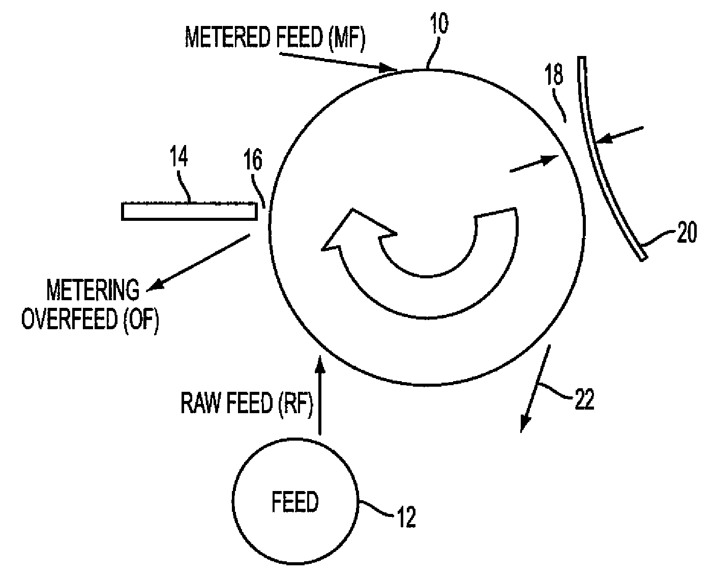
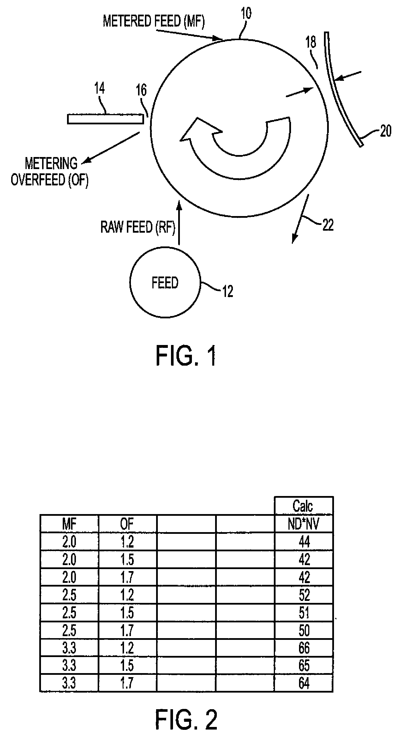
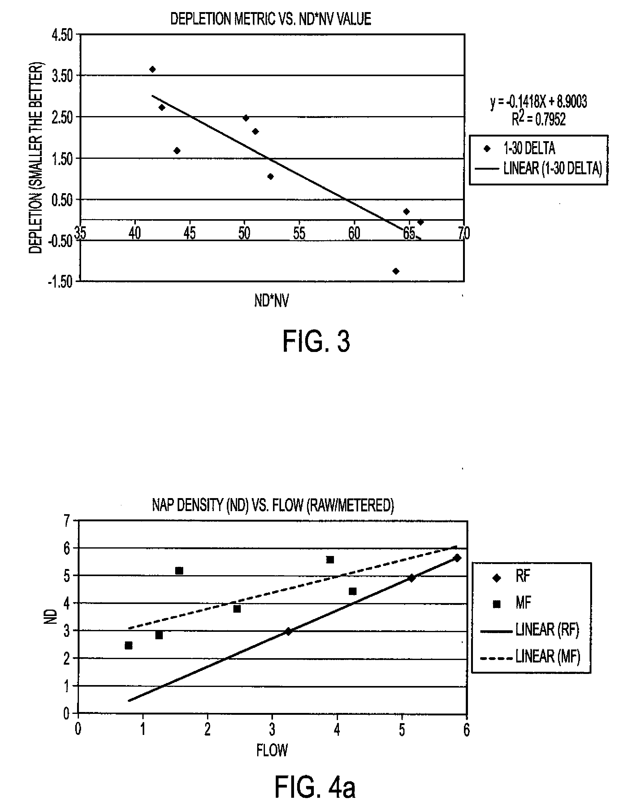
[0013]Experiments were performed to understand the properties of the developer that influenced the development uniformity of flat fields. Flat field uniformity is a critical part of the quality of the output images of a printer. These experiments first concentrated on developing relationships between certain adjustments made to regulate the flow (grams / inch / second) of developer into the toning zone and the resulting changes in the physical properties of the developer.

[0014]FIG. 1 schematically illustrates certain elements of an image development system. The arrangement illustrated in FIG. 1 will be used, together with the following description, to facilitate an understanding of factors considered to be of interest in characterizing effects of developer properties on the development of flat fields. In the illustrated arrangement, developer, including toner (for example, dry ink composed of 8 μm particle size polymeric marking powder at 5%-10% by weight) and a carrier (for example, pe...


PUM


Abstract

Flat field uniformity can be improved in images produced by an image development system having a development roller interposed between a supply of developer and an imaging element. A raw feed of developer is supplied from the developer supply to the development roller to produce both a metered feed of developer and an overfeed of developer, which is returned to the supply, from the raw feed. A plurality of mass densities of developer used in the system and a plurality of developer velocities through the system are determined, and respective product values of those developer mass densities and those developer velocities are thereafter calculated or otherwise determined. A maximum value of the respective product values is identified, and the image development system is then operated so that the maximum product value is produced.

Description

FIELD OF THE INVENTION[0001]This invention concerns a way of improving flat field uniformity in images produced by an image development system having a development roller interposed between a supply of developer and an imaging element.BACKGROUND OF THE INVENTION[0002]In a two-component development system, the ability to apply sufficient developer (toner and carrier) to develop a latent image on a photoconductor is critical to the creation of images with high fidelity and quality. In general practice, developer “flow” is the common metric used to describe the amount of developer delivered to the toning zone per unit time. Flow measurement is accomplished by lowering a gate (2 inches wide) into the developer stream and collecting developer for a specified amount of time (0.5 seconds). This developer is then weighed, and developer flow is reported in units of grams / inch / second. Developer flow has been correlated against certain imaging properties of the developer, such as toning contra...

Claims


Application Information

Patent Timeline
Patent Type & Authority Applications(United States)
IPC IPC(8): G03G15/08
CPCG03G15/0812
Inventor BROWN, KENNETH J.
Owner EASTMAN KODAK CO
Why Eureka
Try Eureka