Gas-insulated high-voltage switchgear

A high-voltage equipment and gas-insulated technology, which is applied in the installation of gas-insulated substations, electrical components, and busbars, can solve the problems of high manufacturing costs and high costs, and achieve sufficient mechanical properties, high mechanical strength, and good traceability.

Inactive Publication Date: 2005-03-09
SIEMENS AG
View PDF1 Cites 4 Cited by
  • Summary
  • Abstract
  • Description
  • Claims
  • Application Information

AI Technical Summary

Problems solved by technology

[0005] However, there is the disadvantage that due to the large annular cavity, the outer conductor usually made of aluminum has a great mass and is thus very expensive to manufacture and transport
The same is the case with funnel-shaped insulators made of expensive casting resins, which require high manufacturing costs to ensure homogeneous dielectric properties

Method used


Image

  • Gas-insulated high-voltage switchgear
  • Gas-insulated high-voltage switchgear

Examples


Embodiment Construction

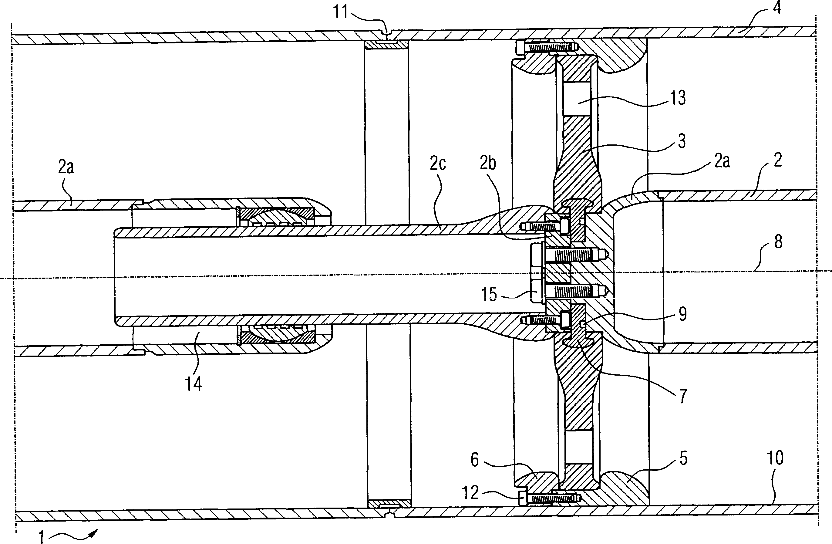
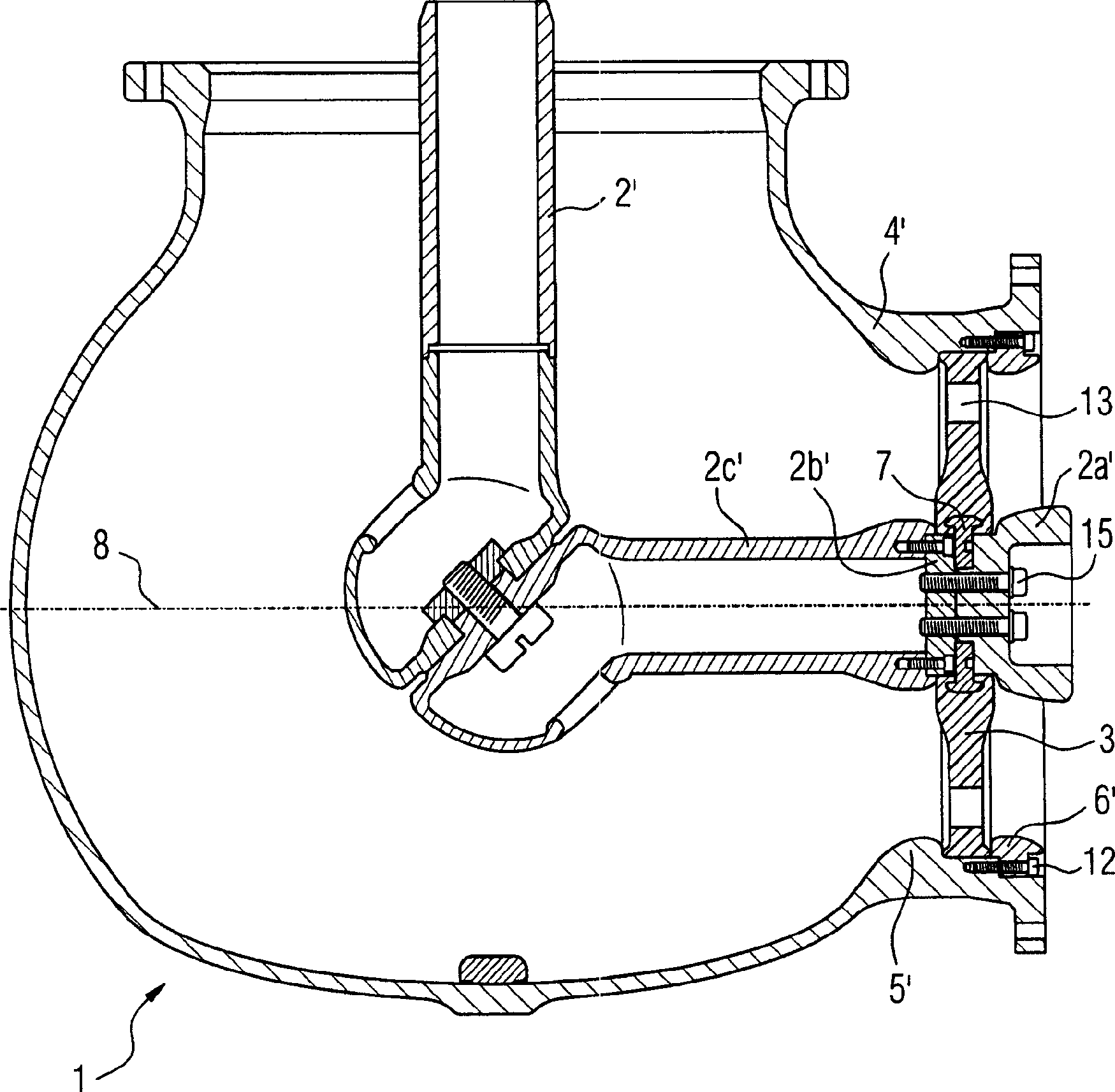
[0028] figure 1A gas-insulated high-voltage installation 1 according to the invention is shown. It is designed in particular for the transmission of high voltages in the range above 250 kV, ie the potential difference between a longitudinally extending inner conductor 2 and an outer conductor can exceed 245 kV in total. The inner conductor 2 is supported in the tubular outer conductor 4 by means of an insulator 3 , the insulator being fastened on the one hand to the inner conductor and on the other hand to the outer conductor by means of a first electrode 5 and a second electrode 6 . The outer conductor consists of tube modules. The pipe modules are joined to each other at the transfer point 11 . The tube is preferably made of aluminum (the inner conductor and all electrodes described here are also preferably made of aluminum unless otherwise stated).

[0029] Insulator 3 is designed as a flat disc, ideal situation is given in this example, that is, insulator 3 is substanti...


PUM


Abstract

Insulators (3) support an inner conductor (2) in a tubular outer conductor (4) and fasten on the inner conductor on one side and on the outer conductor on the other side by means of first (5) and second (6) external electrodes. The insulator acts as a disk and links to a cast mushroom-shaped control electrode (7) towards the inner conductor.

Description

technical field [0001] The invention relates to a gas-insulated high-voltage device. Background technique [0002] Such devices are, for example, prefabricated section by section, the prefabricated sections being delivered to a line and then connected to one another on or in the line by welding, by means of plug connections or by means of flange connections. The prefabricated sections consist of one or more tubular inner conductors and a likewise tubular outer conductor. The inner conductor is fixed in the outer conductor by means of an insulator. Such support insulators, in addition to insulating the equipment section, can also allow air flow in the axial direction through suitable shaping. [0003] For example, DE 19725311 A1 of this type uses a gas-insulated high-voltage system in which at least one inner conductor is supported in a tubular outer conductor by means of an insulator, which is fastened on one side to the inner conductor and on the other side to the outer c...

Claims


Application Information

Patent Timeline
Patent Type & Authority Applications(China)
IPC IPC(8): H02G5/06
CPCH02G5/066
Inventor 马里奥·基珀
Owner SIEMENS AG
Why Eureka
Try Eureka