A wave stirrer for a microwave oven

A technology of agitator and microwave oven, applied in the field of microwave ovens, can solve the problems of microwave leakage, expensive manufacturing, damage to the wave agitator and the inner wall of the furnace cavity, etc., and achieves the effects of low hot spot and spark discharge danger, improved wave impedance, and low-cost production.

Inactive Publication Date: 2014-04-23
ELECTROLUX HOME PROD CORP NV
View PDF15 Cites 0 Cited by
  • Summary
  • Abstract
  • Description
  • Claims
  • Application Information

AI Technical Summary

Problems solved by technology

Sharp edges and small gaps will cause sparkovers or discharge effects that can damage the wave stirrer and the inner walls of the furnace chamber
Damage to the inner walls of the oven cavity can lead to undesired microwave leakage
[0006] State-of-the-art wave mixers often have complex geometries, which are expensive to manufacture
However, wave stirrers with simple geometry and small size do not substantially improve the distribution of electromagnetic energy because the feedback to the magnetron is not high enough

Method used


Image

  • A wave stirrer for a microwave oven
  • A wave stirrer for a microwave oven
  • A wave stirrer for a microwave oven

Examples


Embodiment Construction

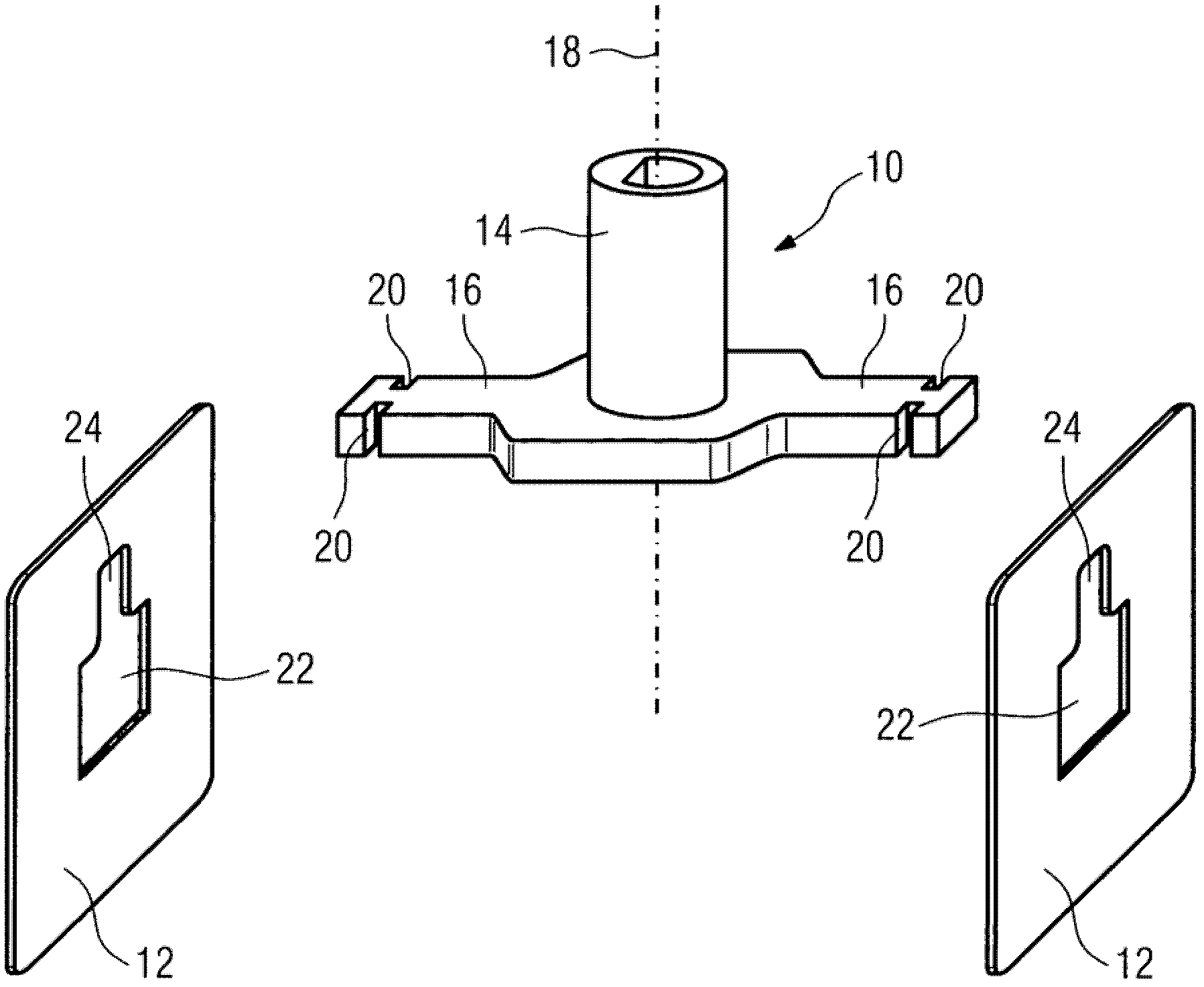
[0033] figure 1 A schematic perspective view of the wave stirrer in a disassembled state according to the first embodiment of the present invention is shown. The wave stirrer includes a holding device 10 and two stirrer blades 12.

[0034] The holding device 10 is made of a dielectric material. Preferably, the holding device 10 is made of ceramic or polymer having high temperature resistance. For example, the holding device 10 is made of LCP.

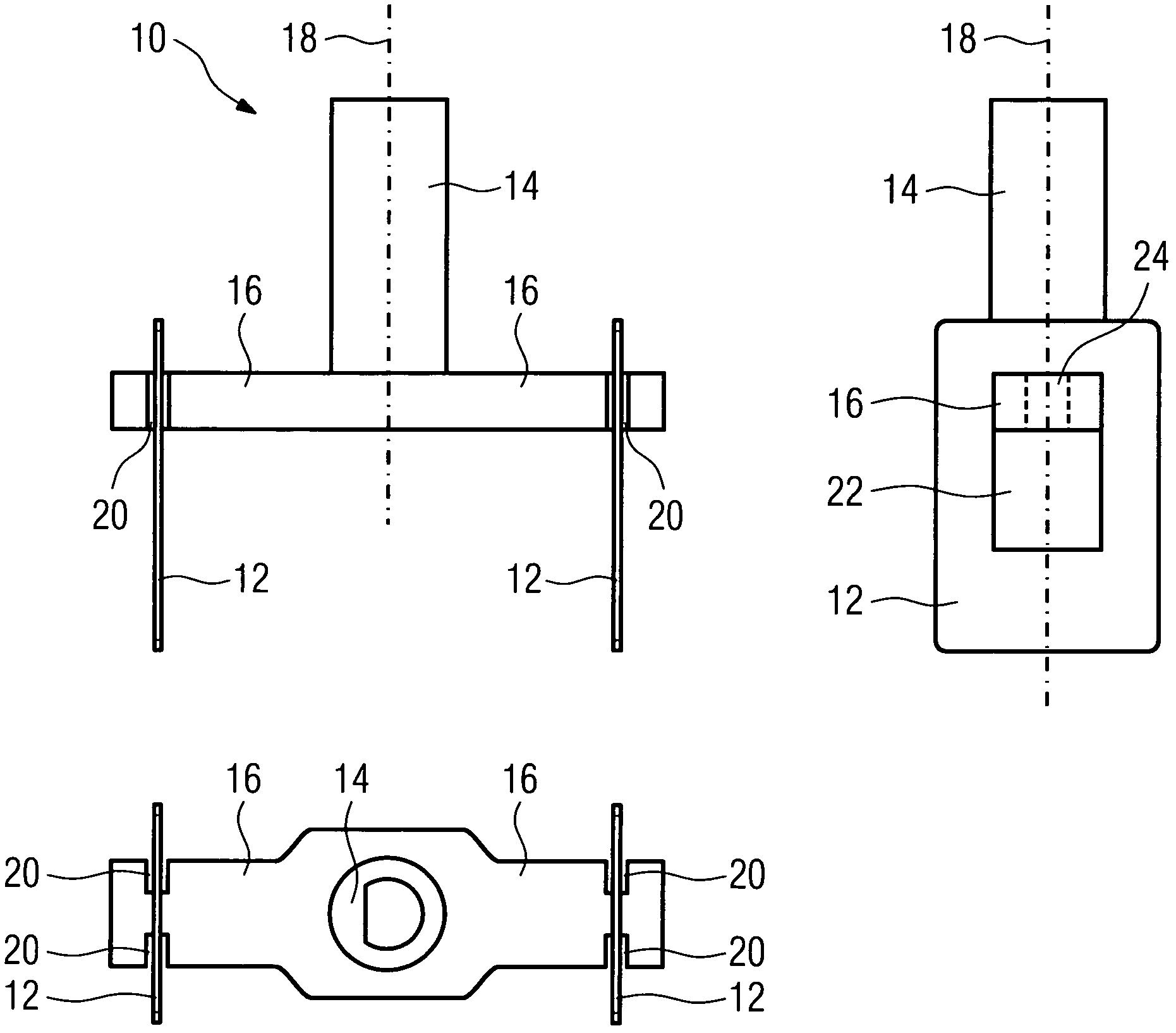
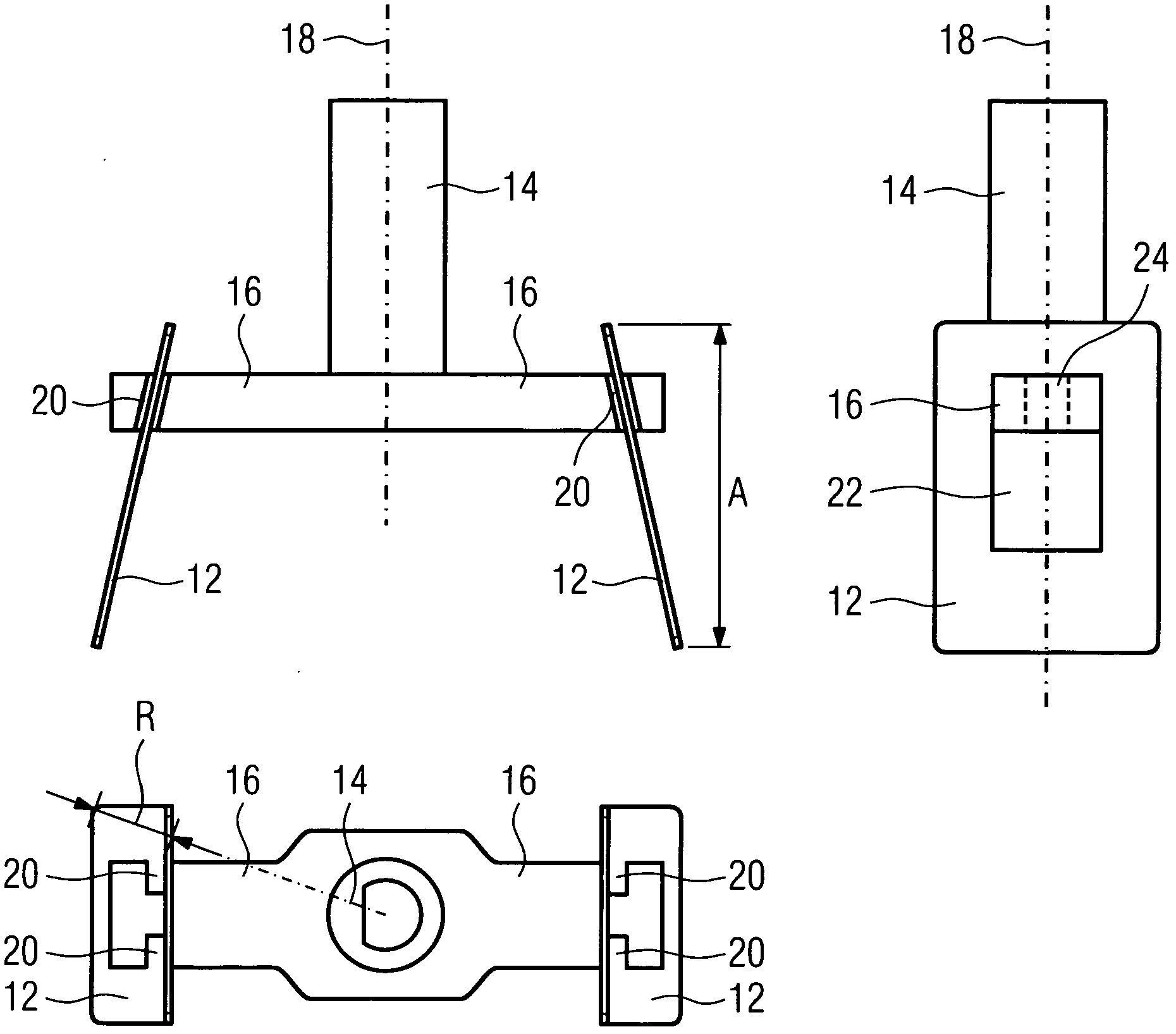
[0035] The holding device 10 includes a shaft 14 and two cantilever arms 16. The shaft 14 extends concentrically along the vertical rotation axis 18. The elongated cantilever 16 is mounted at the lower end of the shaft 14 on opposite sides of the shaft 14. The cantilever 16 extends perpendicular to the shaft 14 along the common axis. Each cantilever 16 protrudes from the rotating shaft 18 in the radial direction. In this example, the two cantilevers 16 are formed as a single piece.

[0036] The cantilevers 16 each include two mounting g...


PUM


Abstract

The present invention relates to a wave stirrer for a microwave oven. The wave stirrer comprises a holding device (10) rotatable around a rotation axis (18) and at least two stirrer blades (12; 26; 28; 34) arranged at the holding device (10). The holding device (10) is made of at least one dielectric material. The stirrer blades (12; 26; 28; 34) are made of at least one conductive material. The maximum axial extension (A) of the stirrer blade (12; 26; 28; 34) along the rotation axis (18) is equal as or bigger than the maximum radial extension (R) of the stirrer blade (12; 26; 28; 34) orthogonal to the rotation axis (18). Further, the present invention relates to a microwave oven with said wave stirrer.

Description

Technical field [0001] The invention relates to a wave stirrer for a microwave oven, which has a holding device and at least two stirrer blades. Furthermore, the present invention relates to a microwave oven including at least one wave stirrer having a holding device and at least two stirrer blades. Background technique [0002] In domestic facilities, microwave ovens have become a very common technology due to its energy efficiency and time saving (compared to ordinary stoves). Microwaves are reflected by metal surfaces such as the walls of the furnace cavity. Therefore, interference makes the microwave energy non-uniformly distributed in the oven cavity, resulting in uneven heating of the food. [0003] In order to make the microwave energy more evenly distributed in the cavity, the microwave oven is equipped with a wave stirrer. The wave stirrer is rotatable and made of conductive material. The wave stirrer is arranged inside the furnace cavity so that the rotation generates...

Claims


Application Information

Patent Timeline
Patent Type & Authority Patents(China)
IPC IPC(8): H05B6/74
CPCH05B6/74
Inventor A-I·茨巴特M·布赖特施韦特A·霍夫曼D·摩尔
Owner ELECTROLUX HOME PROD CORP NV
Why Eureka
Try Eureka