Millipede surface coils

a surface coil and millipede technology, applied in the field of magnetic resonance imaging (mri) apparatus, can solve the problems of lowering the signal to noise ratio, requiring fairly large externally applied bias voltages to completely turn on or off pin diodes, and difficult to achieve a high degree of accuracy, so as to improve the filling factor and minimize the magnetic field “hot spot” around the elements. , the effect of uniform detection sensitivity

Inactive Publication Date: 2012-02-28
AGILENT TECH INC
View PDF22 Cites 4 Cited by
  • Summary
  • Abstract
  • Description
  • Claims
  • Application Information

AI Technical Summary

Benefits of technology

[0010]The present invention realizes a surface coil featuring a high density of rungs thereby achieving increased RF field homogeneity and improved RF conductivity, and without the need of a fixed capacitor associated with each rung element. This is extremely important for small animal imaging where there is insufficient space to accommodate the introduction of even small size chip capacitors. Another advantage of the present invention is that the coil array is fixed to a flexible insulating material and can be shaped to fit closely to the contour of the region of the object that is to be imaged or studied. By using many closely spaced electrically conducting elements the distributed capacitance between adjacent rung elements is sufficient to provide resonance at or near the desired operating frequency thereby eliminating the need for fixed capacitors in series with each rung element.
[0011]In prior art RF coil designs suitable for imaging animals such as rats and mice, the number of rung elements is less than 10. Although the authors argued that the design could be extended to a larger number of elements, the statement is not supported with any kind of explanations or suggestions for such implementation. In fact, the prior arts designs are based on the use of lumped capacitor elements in construction. The physical size of the lumped element components limits the maximum possible number of elements to 10 or less in surface coils for small animals.
[0012]The millipede surface coil of this work has a coil structure with 100 or more rung elements. The elements are similar to those used in the millipede birdcage coil disclosed in U.S. Pat. No. 6,285,189 and assigned to the assignee as the present invention. Since the coil has lots of elements or rungs, the magnetic field “hot spot” around the elements are minimized. As the result, millipede surface coils can be positioned very close to a sample to improve the filling factor and provide uniform detection sensitivity close to the sample surface. Also the distributed capacitor design of millipede surface coil helps to minimize the stray dielectric loss in the sample and to reduce the frequency shift due to the sample loading. According to an embodiment of the invention the coil can be operated in two modes, with the RF fields of the two modes being orthogonal, and can be driven in quadrature.
[0013]Means for independently tuning and matching the two modes of the millipede surface coil have been devised. Also an active detuning circuit has been devised using an inductor circuit with two pin diodes that operates in the off mode with zero bias voltage.

Problems solved by technology

The problem that occurs in these systems arises from the coupling between the two coils.
In addition, any noise in the transmitter circuit is coupled into the receiver thereby lowering the signal to noise ratio.
This in practice is difficult to do with a high degree of accuracy, making it desirable to find other ways to reduce these undesirable effects.
This has been found to work, however it requires fairly large externally applied bias voltages to completely turn on or off a pin diode when large RF voltages are present.
Both of these patents require fixed capacitors either in series with the rung elements or between rung elements, which because of their size, cause problems particularly in surface coils for the imaging of small animals.
In addition fixed capacitors typically have a different magnetic susceptibility that the surrounding region thereby causing unwanted gradients in the DC magnetic field Bo.

Method used


Image

  • Millipede surface coils
  • Millipede surface coils
  • Millipede surface coils

Examples


Embodiment Construction

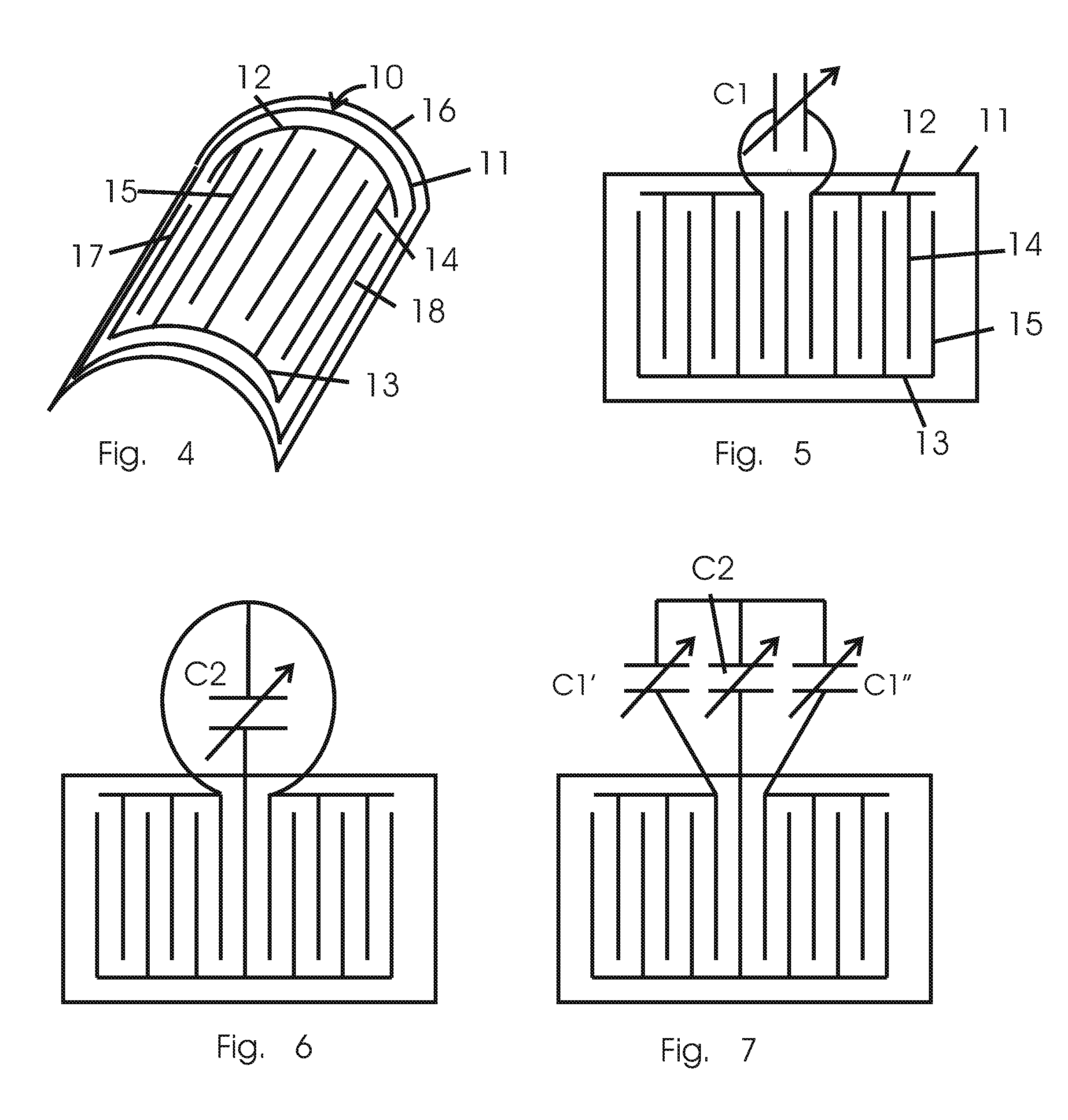
[0027]The RF coil used for transmitting radio frequency fields to the object or animal and / or detecting the responding RF fields from the object form the subject of this invention. The subject work is directed particularly toward coils that can be effectively used for small animals such as mice or rats, or small samples of material. To obtain the highest sensitivity the coil should be placed as close as possible to the region of the object being imaged. This might be, for example, the brain of a mouse or rat, or a small region near the surface of a larger animal or object.

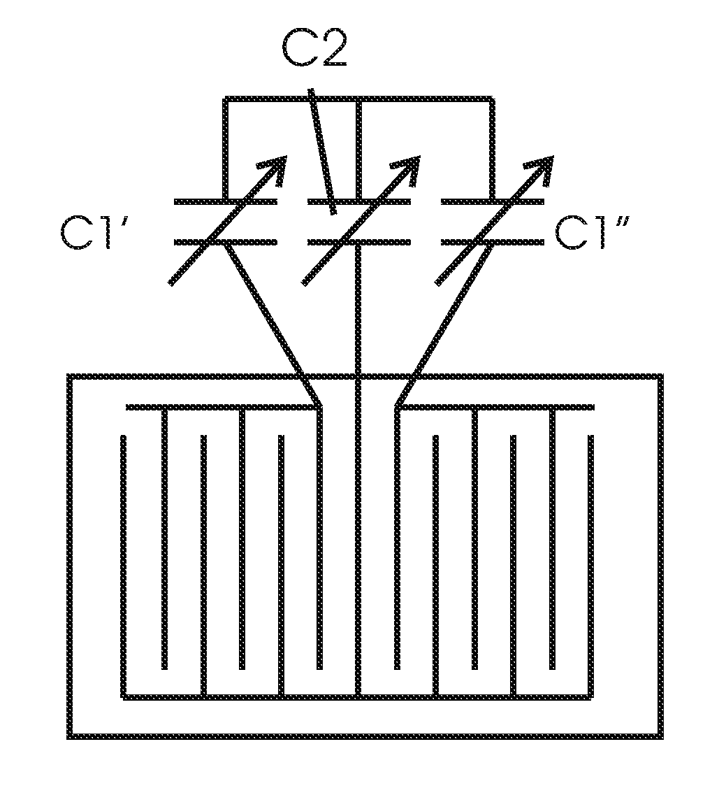
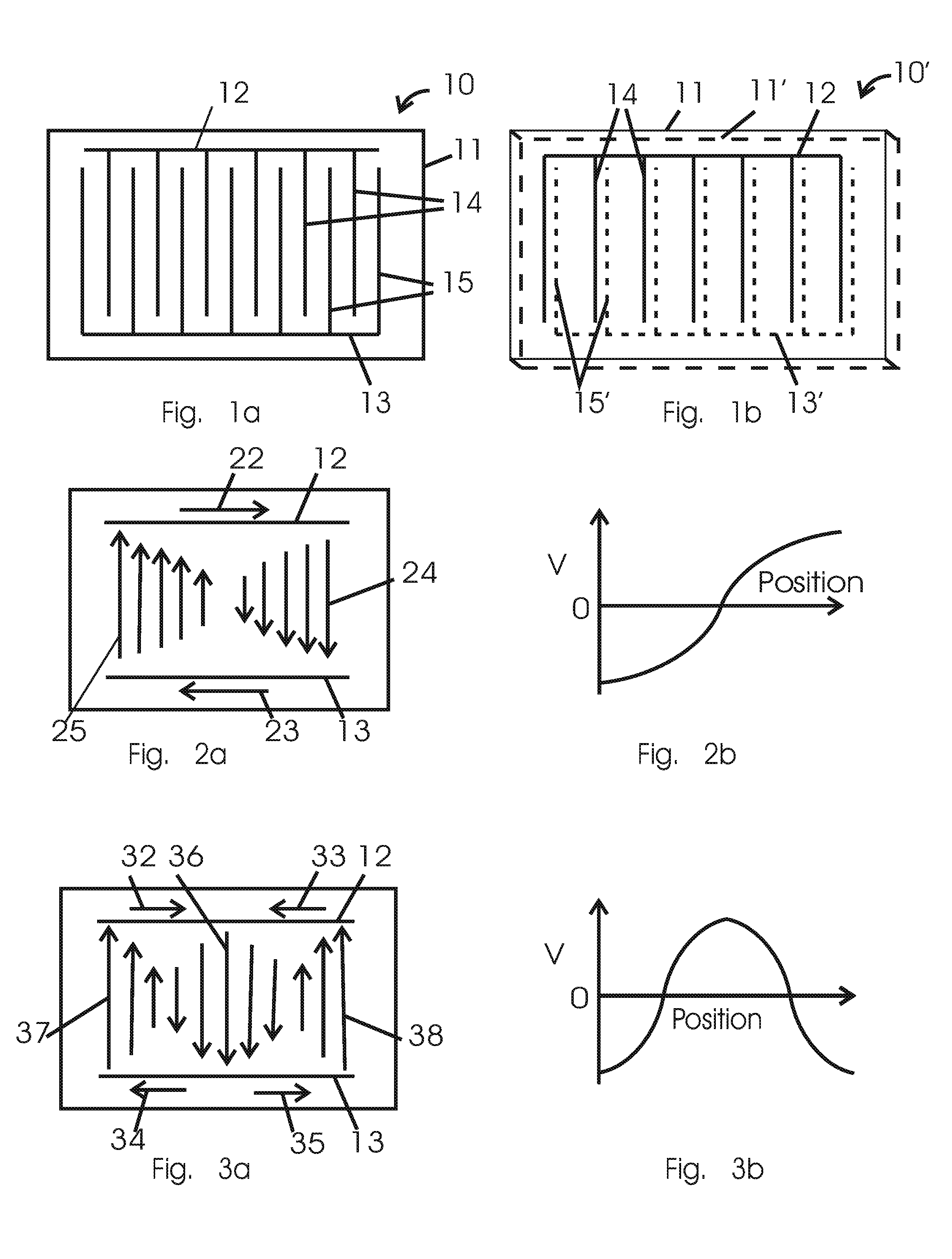
[0028]FIG. 1a shows a millipede surface coil 10 illustrating one aspect of the invention. The millipede surface coil 10 of FIG. 1a comprises a first electrically conducting end strip 12, and a second electrically conducting end strip 13, which is spaced apart and parallel to the first conducting end strip. Typically there are a hundred or more conducting rungs elements, 14, 15, placed between the two end strips, le...


PUM


Abstract

A low pass RF ladder coil, which is named as a millipede surface coil, comprises a first and a second conductor end strips running parallel to each other. A set of rung elements are placed between them, alternate rung elements are connected to the first and second strip respectively. The number and spacing of the rung elements are sufficient for resonating the coil at the desired imaging frequency. This millipede surface coil may have 100 or more rung elements. Fixed and variable capacitors are provided for separately tuning and matching the first and second mode resonant frequencies, and for coupling and impedance matching the two modes to external circuits. An active detuning is provided that detunes the ladder coil when a separate RF coil is transmitting.

Description

FIELD OF THE INVENTION[0001]The subject work relates to the field of magnetic resonance imaging (MRI) apparatus and pertains to RF surface coil geometry for the excitation and observation of magnetic resonance signals.BACKGROUND OF THE INVENTION[0002]The conventional apparatus for MRI comprises a magnet producing a strong DC magnetic field Bo in the imaged object. Typically the magnet is a superconducting magnet and its axis may either be oriented vertically or horizontally, depending upon the design. Within a bore is a set of gradient coils producing a distribution of magnetic fields within the object being imaged as is required for MRI. One or more RF coils are placed near the sample to produce an RF magnetic field B1 to stimulate the magnetic resonance of a given nuclear species in the object, and the same coil or a separate coil to detect any resonances that are produced in the object. The apparatus includes a RF transmitter to generate the required RF current supplied to the st...

Claims


Application Information

Patent Timeline
Patent Type & Authority Patents(United States)
IPC IPC(8): G01V3/00
CPCG01R33/341G01R33/3628
Inventor WONG, WAI HASUKUMAR, SUBRAMANIAM
Owner AGILENT TECH INC
Why Eureka
Try Eureka