System for the one-sided generation of magnetic fields for the multidimensional encoding of magnetic particles and method of operation thereof

a magnetic particle and one-sided generation technology, applied in the field of magnetic particle imaging with one-sided coil assemblies, can solve the problems of low signal-to-noise ratio, low scanning speed, and low signal-to-noise ratio, and achieve the effect of simplifying driving circuits and enhancing the field homogeneity of said magnetic field components

Pending Publication Date: 2022-05-26
JULIUS MAXIMILIANS UNIV WURZBURG
View PDF0 Cites 4 Cited by
  • Summary
  • Abstract
  • Description
  • Claims
  • Application Information

AI Technical Summary

Benefits of technology

[0046]Thus, using the first, second and third time varying currents, the FFL may be rotated and displaced along two directions perpendicular to a current extension direction of the FFL, respectively, thereby enabling a measurement of magnetic particles in said probe volume spatially resolved along three dimensions.
[0047]In principle, the third time varying current could also be applied to the inner coil and / or the outer coil of a plurality, and in particular all, of the circumferentially distributed coil assembly sectors in phase, to generate said magnetic field component along the coil assembly axis. However, providing a dedicated radial displacement coil may enhance a field homogeneity of said magnetic field component perpendicular to the coil assembly axis and therefore a linearity of a radial displacement of the FFL in the probe volume. Further, providing a dedicated radial displacement coil may simplify driving circuits and may allow defining a sharp radial displacement frequency. In some embodiments, the radial displacement coil is also used to measure a response of the magnetic particles in the probe volume.

Problems solved by technology

Detection systems using FFPs to spatially select sequentially investigated regions suffer from low signal-to-noise ratio and low scanning speed.
At the same time, both the three dimensional detection of a presence of magnetic particles based on an FFL as well as a measurement based on rotational drift spectroscopy / imaging rely on the ability to produce a controlled rotation of a magnetic field distribution and currently suffer from control and speed limitations due to mechanically moving parts.
Moreover, the known one-sided coil geometries often suffer from strongly asymmetric fields and / or low gradients along the direction going away from the coils.

Method used


Image

  • System for the one-sided generation of magnetic fields for the multidimensional encoding of magnetic particles and method of operation thereof
  • System for the one-sided generation of magnetic fields for the multidimensional encoding of magnetic particles and method of operation thereof
  • System for the one-sided generation of magnetic fields for the multidimensional encoding of magnetic particles and method of operation thereof

Examples


Embodiment Construction

[0069]The features and numerous advantages of the method, computer program and system according to the present invention will best be understood from a detailed description of preferred embodiments with reference to the accompanying drawings, in which:

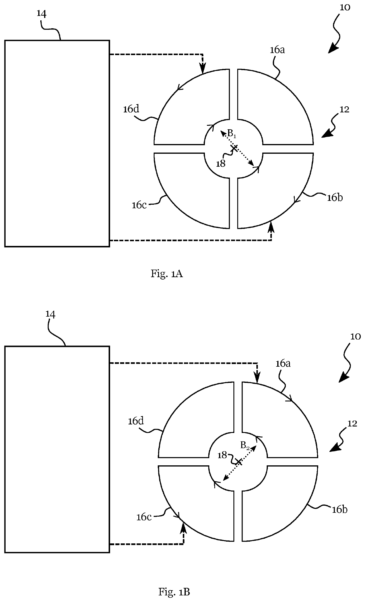
[0070]FIG. 1 schematically shows an example of a system for one-sided measuring a presence of magnetic particles;

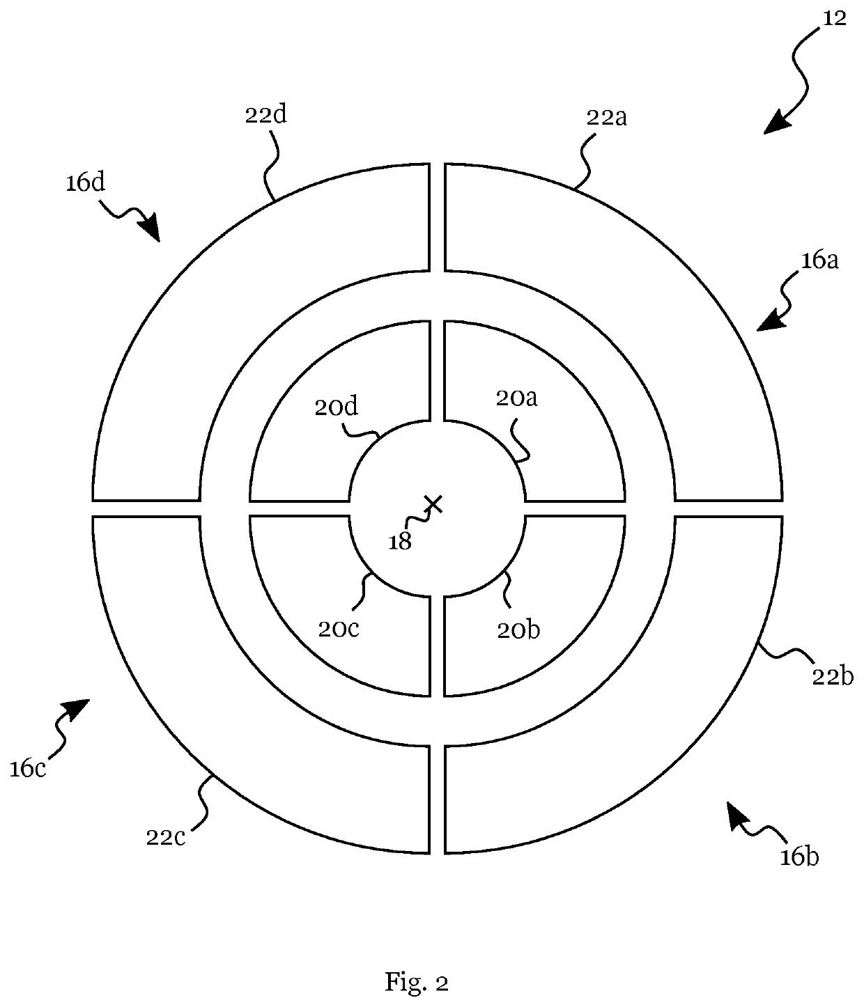
[0071]FIG. 2 illustrates a schematic one-sided coil assembly according to an example;

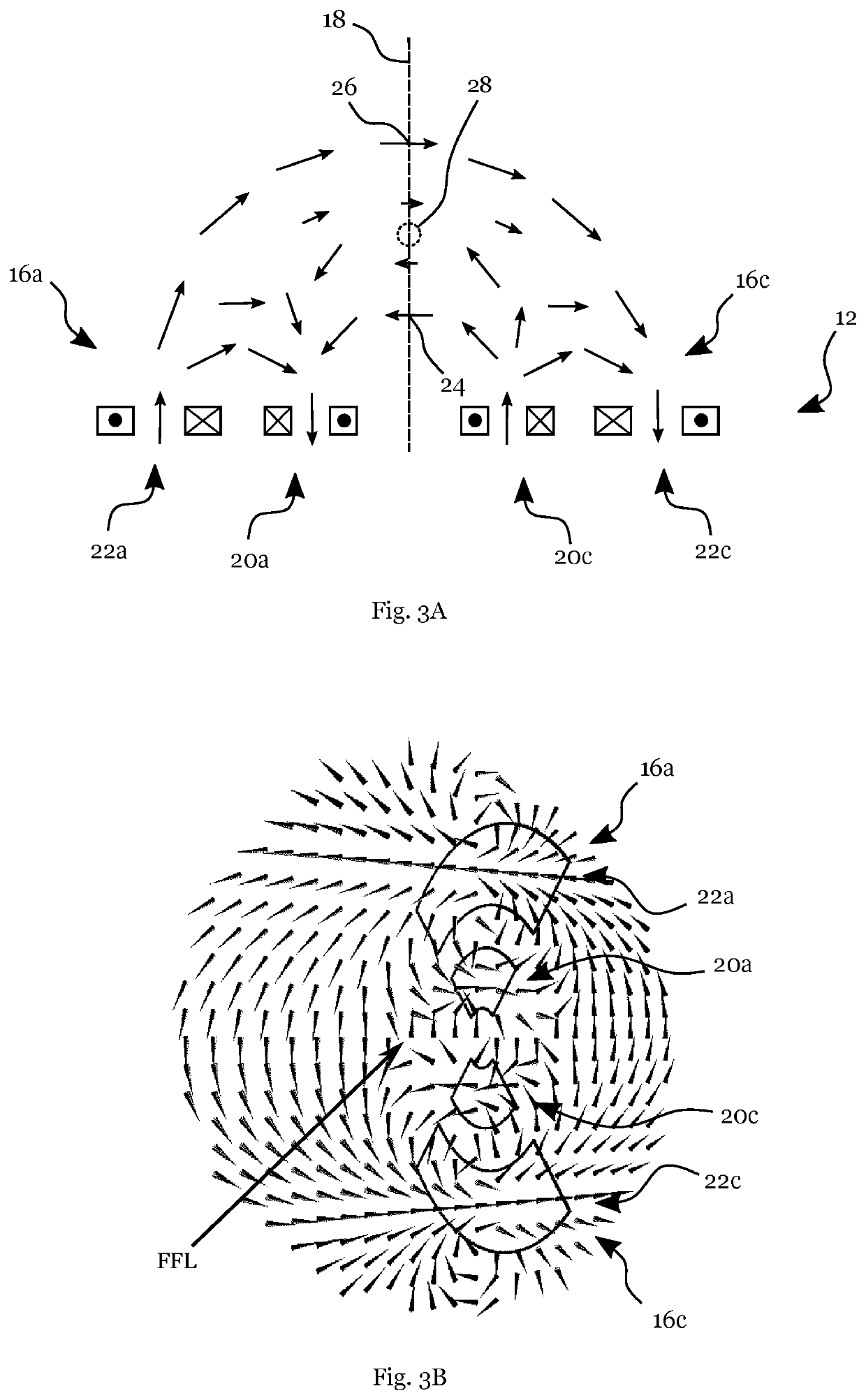
[0072]FIG. 3A schematically illustrates a side view of magnetic field directions generated by oppositely arranged coil assembly sectors in an exemplary current configuration;

[0073]FIG. 3B schematically illustrates a perspective view of magnetic field directions generated by oppositely arranged coil assembly sectors in an exemplary current configuration;

[0074]FIG. 4A, 4B illustrate two perspective views of oppositely arranged coil assembly sectors superposed with a schematic representation of a field free line generated in an exemplary curren...


PUM

PropertyMeasurementUnit
angleaaaaaaaaaa
diameteraaaaaaaaaa
angleaaaaaaaaaa

Abstract

A system for one-sided measuring a presence of magnetic particles in a probe volume comprises a one-sided coil assembly and a current controller, wherein the one-sided coil assembly is arranged around a central coil assembly axis for generating a rotating magnetic field distribution and comprises at least 3, preferably at least 4, circumferentially distributed coil assembly sectors, wherein the current controller is configured to generate a time varying current in each of said coil assembly sectors, said time varying current comprising a periodic modulation with a rotation frequency and phase shifted between adjacent coil assembly sectors to generate a magnetic field rotating in a plane perpendicular to the coil assembly axis, said magnetic field rotating with a rotation frequency associated with a frequency of said periodic modulation, and wherein the system is configured for measuring said presence of magnetic particles in said probe volume with said one-sided coil assembly.

Description

FIELD OF THE INVENTION[0001]The present invention is in the field of magnetic imaging technology. More precisely, the present invention relates to magnetic particle imaging with one-sided coil assemblies.BACKGROUND[0002]The treatment and diagnosis of medical conditions increasingly relies on imaging technology. Commonly used methods such as X-ray Computed Tomography (CT) and Positron Emission Tomography (PET) provide short acquisition times with high spatial resolution but expose the patient to high-energy radiation.[0003]In contrast, imaging technologies based on magnetic fields use the characteristic response of atoms, molecules or particles in the human body to a time varying magnetic field distribution to provide three-dimensional images of the patient's body. For example, nuclear magnetic resonance (NMR) uses the response of hydrogen atoms in the patient's body to microwave fields applied alongside magnetic field gradients to infer the concentration and the position of the hydr...

Claims


Application Information

Patent Timeline
Patent Type & Authority Applications(United States)
IPC IPC(8): G01R33/12G01R33/00A61B5/0515
CPCG01R33/1276A61B5/0515G01R33/0094G01R33/028
Inventor VOGEL, PATRICKRÜCKERT, MARTIN
Owner JULIUS MAXIMILIANS UNIV WURZBURG
Why Eureka
Try Eureka