Magnet configuration with a superconducting magnet coil system and a magnetic field forming device for magnetic resonance spectroscopy

a superconducting magnet coil and magnetic field technology, applied in the direction of superconductor device manufacture/treatment, geological measurements, reradiation, etc., can solve the problems of enlarge the fringe field, lose valuable space for magnet windings, and increase the current required in certain shim coils, etc., to achieve the effect of simple implementation, low cost and great effect of magnetic material

Inactive Publication Date: 2014-05-08
BRUKER BIOSPIN
View PDF5 Cites 5 Cited by
  • Summary
  • Abstract
  • Description
  • Claims
  • Application Information

AI Technical Summary

Benefits of technology

[0010]One considerable advantage of recesses in a cylindrically symmetric field shaping device made of magnetic material is the possibility of improving the field homogeneity of the magnet assembly in the working volume without additional material. In principle, the objective of improved field homogeneity could also be achieved with additional magnetic material, which would be glued, for example, onto the field device. However, this could only be achieved if space for such field corrections were provided from the outset, which would enlarge the magnet assembly and render it more expensive.
[0028]In embodiments of the inventive magnet assembly that have non cylindrically symmetric recesses in the form of through-holes through the field shaping device, the holes can also be cut out with a laser beam. An essential advantage of the laser method is the very high mechanical precision, enabling even complicated shapes to be produced with the utmost precision.

Problems solved by technology

This results in the loss of valuable space for magnet windings, which makes the magnets more expensive and enlarges the fringe field.
For large deviations of the coefficients from their setpoint, the current required in certain shim coils may be too high and the magnetic field of the magnet assembly cannot be corrected as desired.
Alternately, it might not be possible to correct for a problematic coefficient in the expansion of the magnetic field according to the spherical harmonic functions because no corresponding shim coil is provided.
In such a situation, an expensive repair of the magnet system is required in which part of the magnet assembly has to be replaced.

Method used


Image

  • Magnet configuration with a superconducting magnet coil system and a magnetic field forming device for magnetic resonance spectroscopy
  • Magnet configuration with a superconducting magnet coil system and a magnetic field forming device for magnetic resonance spectroscopy
  • Magnet configuration with a superconducting magnet coil system and a magnetic field forming device for magnetic resonance spectroscopy

Examples


Embodiment Construction

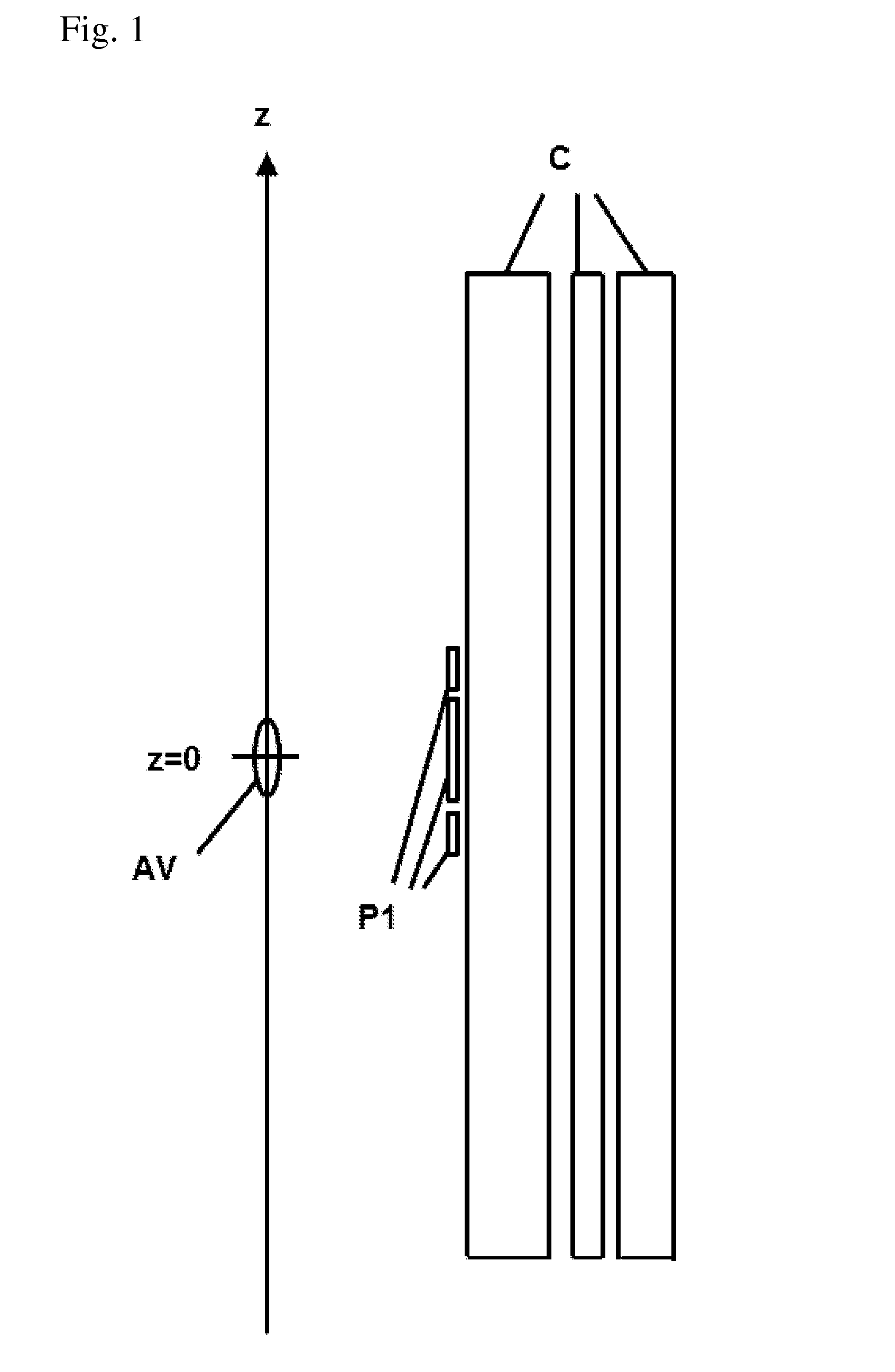
[0038]Based on FIG. 1, an embodiment of the inventive magnet assembly is shown that comprises a magnet coil system C and a magnetic field shaping device P1. At least part of the field shaping device P1 is typically located nearer to the z-axis than is the magnet coil system C. In this case, it consists of 3 rings. A working volume AV is disposed on the z-axis about z=0.

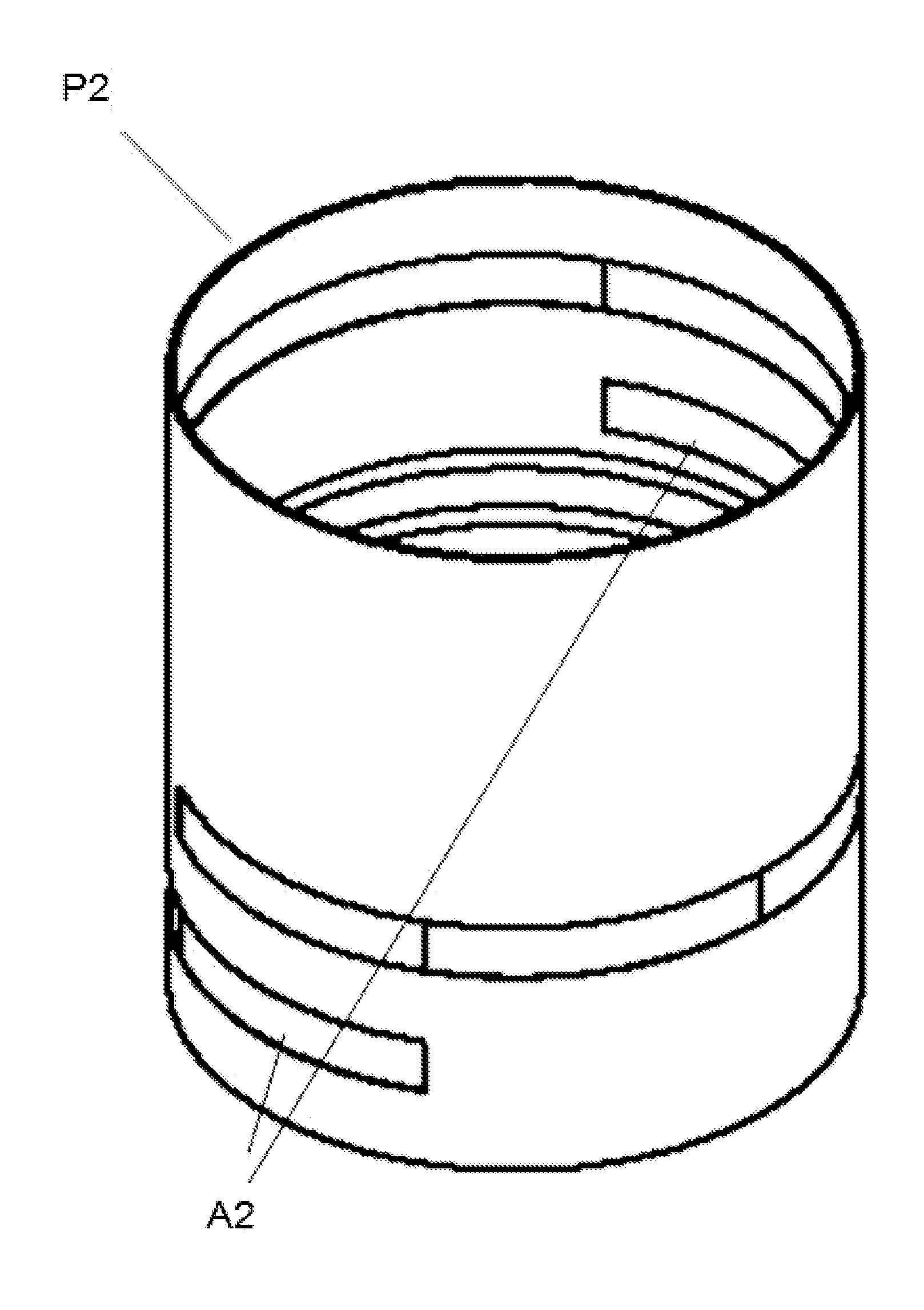
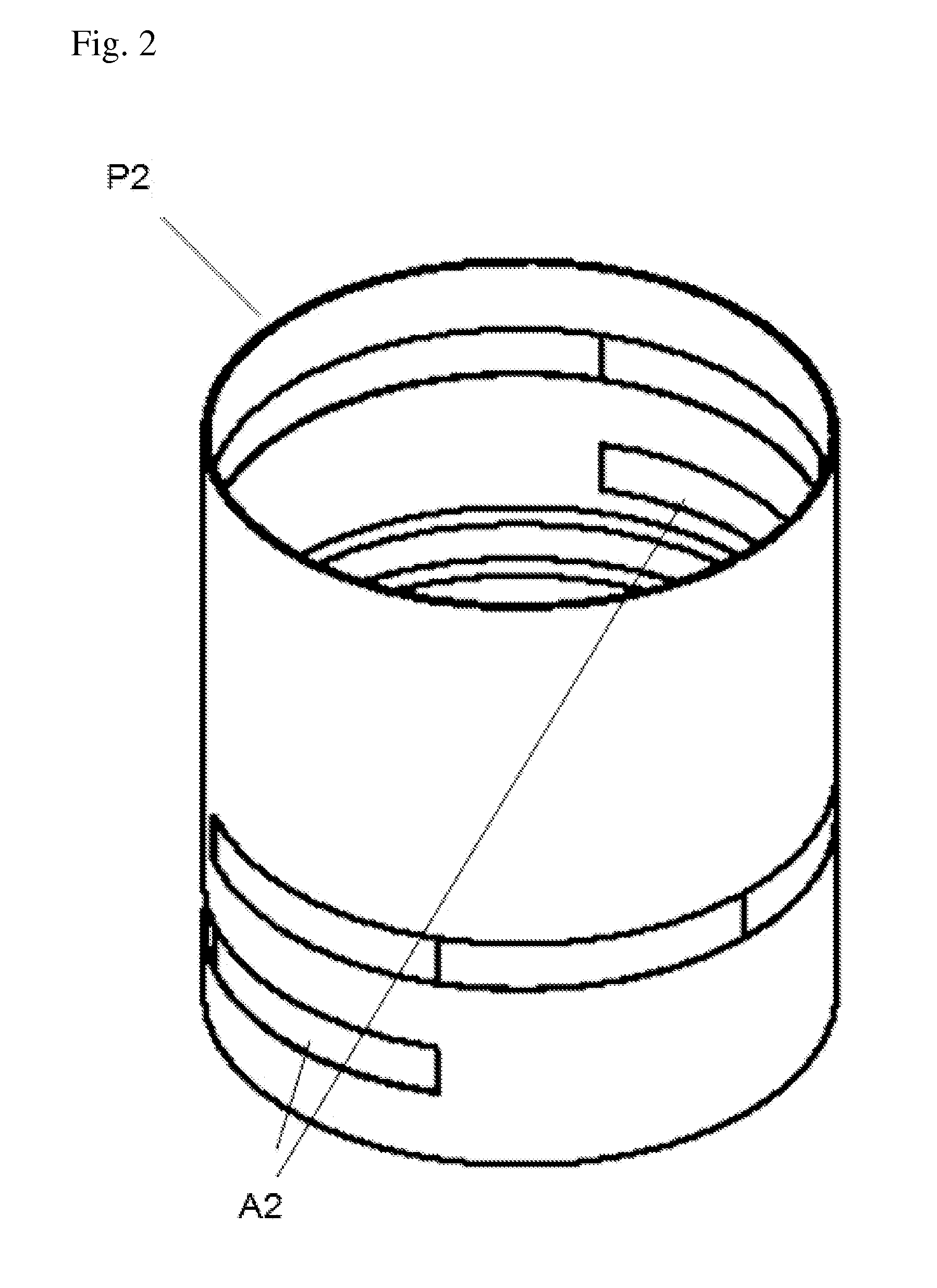
[0039]FIG. 2 shows an inventive field shaping device that typically exhibits non cylindrically symmetric recesses A2 on the inner and outer sides of the field shaping device. These recesses can in principle have shapes and depths of any degree of complication. In practice, however, simple shapes are preferred because the influence of the recesses on the field profile of the magnet assembly is then easier to calculate.

[0040]FIG. 3 shows an inventive field shaping device with through recesses for targeted changing of the B21 coefficients in the magnetic field expansion of the magnet assembly according to the spherical h...


PUM

PropertyMeasurementUnit
internal diameteraaaaaaaaaa
thicknessaaaaaaaaaa
heightaaaaaaaaaa

Abstract

A magnet assembly has a field shaping device (P1) that is cylindrically symmetric with respect to the z-axis and made of magnetic material. At least parts of the field shaping device have a radial distance from the z-axis of less than 80 millimeters and compensate for at least one of the inhomogeneous field parts An0·zn of the magnet coil system. The field shaping device has one or more non cylindrically symmetric recesses, which are constituted such that at least a coefficient Anm or Bnm in the magnetic field expansion of the magnet assembly according to the spherical harmonic functions is reduced by at least 50%. In this way, the field homogeneity of the working volume can be substantially increased in a simple manner and without increasing the volume of the magnet assembly, wherein only a few iterations are required to optimize the magnet assembly.

Description

[0001]This application claims Paris convention priority of DE 10 2012 220 126.2 filed Nov. 5, 2012 the entire disclosure of which is hereby incorporated by reference.BACKGROUND OF THE INVENTION[0002]The invention concerns a magnet assembly for use in an apparatus for magnetic resonance spectroscopy with a superconducting magnet coil system for producing a magnetic field in the direction of a z-axis in a working volume disposed on the z-axis about z=0, wherein the field of the magnet coil system in the working volume has at least one inhomogeneous part An0·zn, where n≧2, whose contribution to the total field strength on the z-axis about z=0 varies with the nth power of z, and wherein a field shaping device that is cylindrically symmetric with respect to the z-axis made of magnetic material is provided, which at least in parts has a radial distance from the z-axis of less than 80 millimeters and compensates for at least one of the inhomogeneous field parts An0·zn of the magnet coil sy...

Claims


Application Information

Patent Timeline
Patent Type & Authority Applications(United States)
IPC IPC(8): G01R33/3815G01R33/38
CPCG01R33/3802G01R33/3815G01R33/3873Y10T29/49014
Inventor BOVIER, PIERRE-ALAINKUEBLER, GUENTER
Owner BRUKER BIOSPIN
Why Eureka
Try Eureka