
Wavy micro gas chromatography column

Active Publication Date: 2016-09-15
UNIV OF ELECTRONIC SCI & TECH OF CHINA
View PDF2 Cites 5 Cited by
  • Summary
  • Abstract
  • Description
  • Claims
  • Application Information

AI Technical Summary

Benefits of technology

The present invention involves a new design for a micro chromatography groove that increases the efficiency of separating gas molecules using a wavy channel structure instead of micro posts. This design decreases the laminar flow effect and increases the interaction between gas molecules and the stationary phase, resulting in higher separation efficiency. Additionally, using a suitable first arc ensures enhanced contact between gas molecules and the stationary phase without prolonging the analysis time. The wavy channel structure also increases the surface area of the stationary phase, which increases the gas distribution coefficient and the column efficiency.

Problems solved by technology

With the social development, the industrialization process, and the continuously rising living standard, the environmental pollution causes more and more problems.
Although the conventional gas chromatograph has the strong mixture separation ability, the conventional gas chromatograph has the problems of large volume, heavy weight, long separation time, and relatively high energy consumption.
Thus, for the open tubular column, the airflow at the center is fastest and at the edge is slowest, leading to a laminated flow distribution for a deep vertical groove, which is disadvantageous for the contact between the gas molecules and the stationary phase.
Although the semi-packed column has the higher separation efficiency than the open tubular column, the MEMS machining of the semi-packed column is more difficult since the much smaller size and finer substructures are needed to be realized.

Method used


Image

  • Wavy micro gas chromatography column
  • Wavy micro gas chromatography column
  • Wavy micro gas chromatography column

Examples


Embodiment Construction

[0044]The present invention is further illustrated with a preferred embodiment. One skilled in the art will easily know the advantages and the benefits of the present invention from the preferred embodiment and understand that the embodiment of the present invention as shown in the drawings and described below is exemplary only and not intended to be limiting.

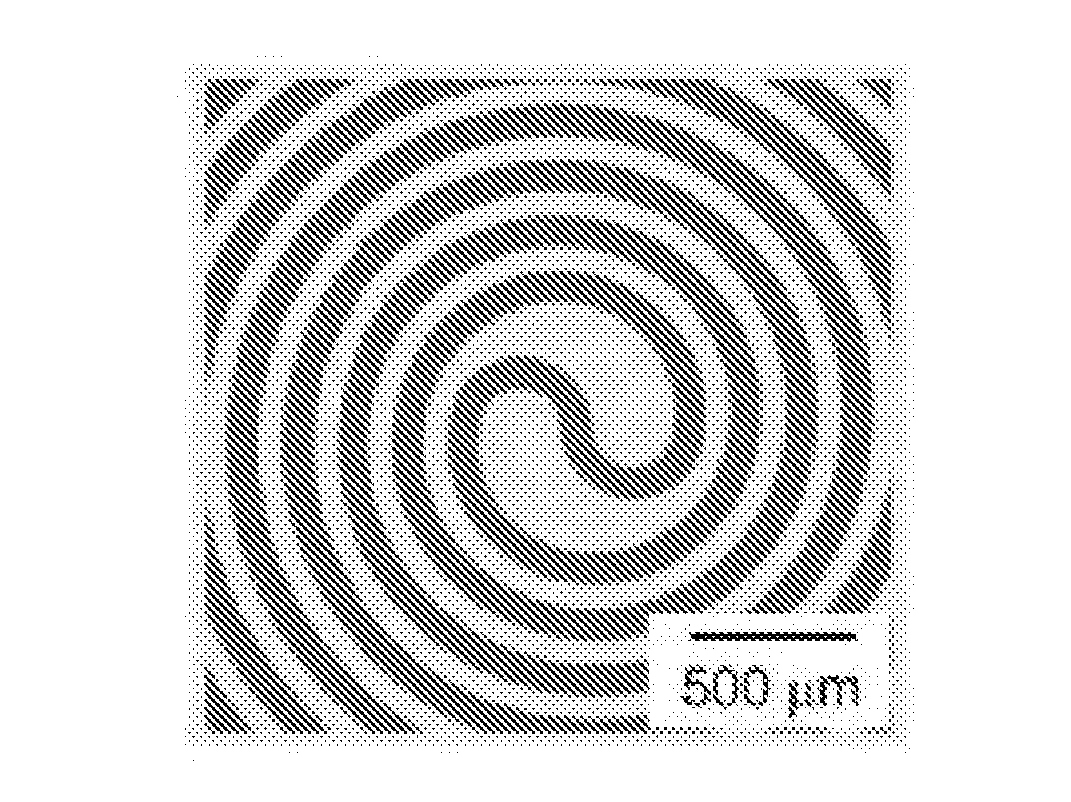
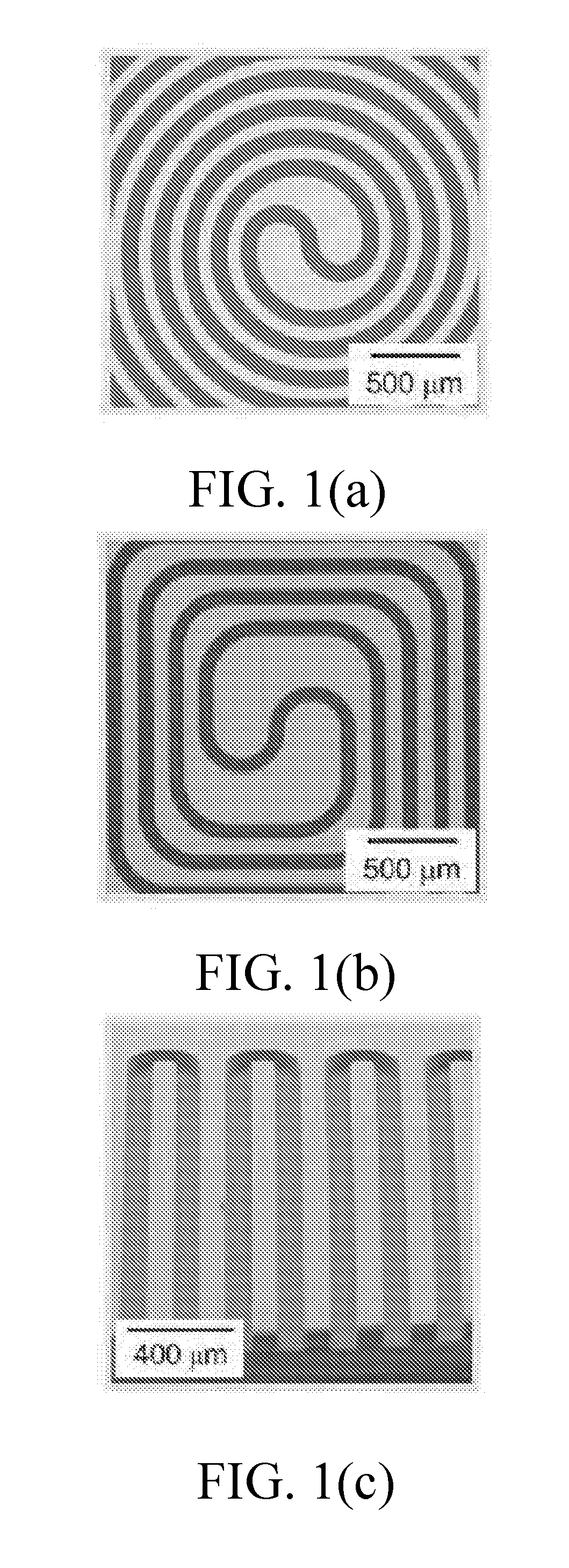
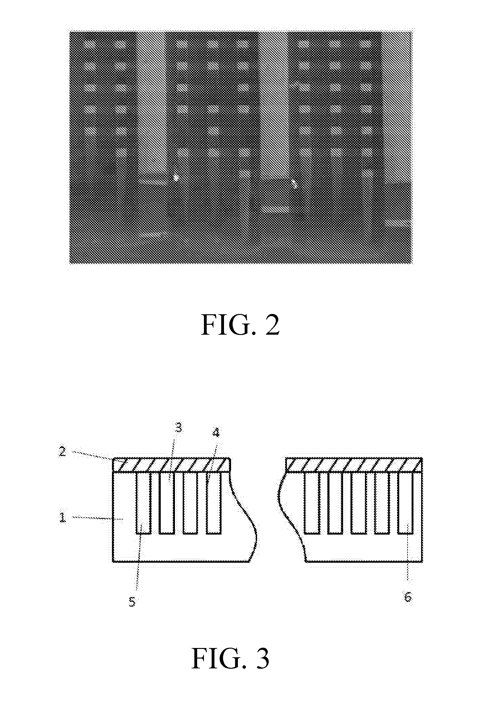
[0045]According to a preferred embodiment of the present invention, a wavy micro gas chromatography column comprises a silicon substrate 1 and a glass cover 2 (7740 glass) bonded to the silicon substrate 1. A groove 3, having a rectangular cross section, is etched on the silicon substrate 1. After being covered by the glass cover 2, the groove 3 is sealed and a micro channel is formed. Four inner walls of the micro channel are coated by a stationary phase film 4. A cross sectional view of the wavy micro gas chromatography column is showed in FIG. 3. The micro channel comprises multiple wavy channel sections. A projection figure...


PUM


Abstract

A wavy micro gas chromatography column includes a silicon substrate and a bonded glass cover. A micro channel having a rectangular cross section is etched on the silicon substrate and coated with a stationary phase film. A projection figure of the micro channel on the silicon substrate includes multiple regular wavy curves. Each wavy curve is formed through alternately connecting first upper arcs with first lower arcs. Because the groove has a curving structure, the carrier gas velocity is decreased as the increase of the arc angle, resulting in an improvement of the flow uniformity at the zones between two adjacent bends but also an enlarging nonsymmetric distribution at the bends. Thus, an optimal curving structure can make the overall flow more even, and in turn achieve a better separation performance compared to the straight channel columns. Meanwhile, a wavy channel realizes a longer column length on a given area.

Description

CROSS REFERENCE OF RELATED APPLICATION[0001]The application claims priority under 35 U.S.C. 119(a-d) to CN 201510577996.7, filed Sep. 11, 2015.BACKGROUND OF THE PRESENT INVENTION[0002]1. Field of Invention[0003]The present invention relates to a technical field of gas chromatography, and more particularly to a wavy micro gas chromatography column.[0004]2. Description of Related Arts[0005]With the social development, the industrialization process, and the continuously rising living standard, the environmental pollution causes more and more problems. The emergency monitoring requires the environmental monitoring department to accurately identify the type, the concentration, the toxicity, and the distribution of the pollutant as quickly as possible. The portable gas chromatograph has the advantages of small volume, light weight, battery power supply and on-site operation. It can meet the requirements of different analysis environments and is generally able to qualitatively analyze the ...

Claims


Application Information

Patent Timeline
IPC IPC(8): G01N30/02
CPCG01N2030/025G01N30/02G01N30/6086G01N30/6095
Inventor DU, XIAOSONGYUAN, HUANZHAO, XULANWU, PENGLINJIANG, YADONG
Owner UNIV OF ELECTRONIC SCI & TECH OF CHINA
Learn More