Centrifugal filtration device

a centrifugal filtration and centrifugal technology, applied in vortex flow apparatus, steam separation arrangement, separation process, etc., can solve the problems of poor filtration efficiency, ineffective use of swirly flow to separate particles and gas, etc., and achieve high separation efficiency

Active Publication Date: 2021-09-14
SON JEONG HWA +2
View PDF25 Cites 0 Cited by
  • Summary
  • Abstract
  • Description
  • Claims
  • Application Information

AI Technical Summary

Benefits of technology

[0004]The main object of the present invention is to provide a centrifugal filtration device which has high separation efficiency.

Problems solved by technology

However, the conventional filtration device has a poor configuration of the housing and the guiding mechanism, which results in collision and friction between the particle-containing gas and the filtration device so that the conventional filtration device cannot effectively utilize swirly flow to separate the particles and the gas and has poor filtration efficiency.

Method used


Image

  • Centrifugal filtration device
  • Centrifugal filtration device
  • Centrifugal filtration device

Examples


Embodiment Construction

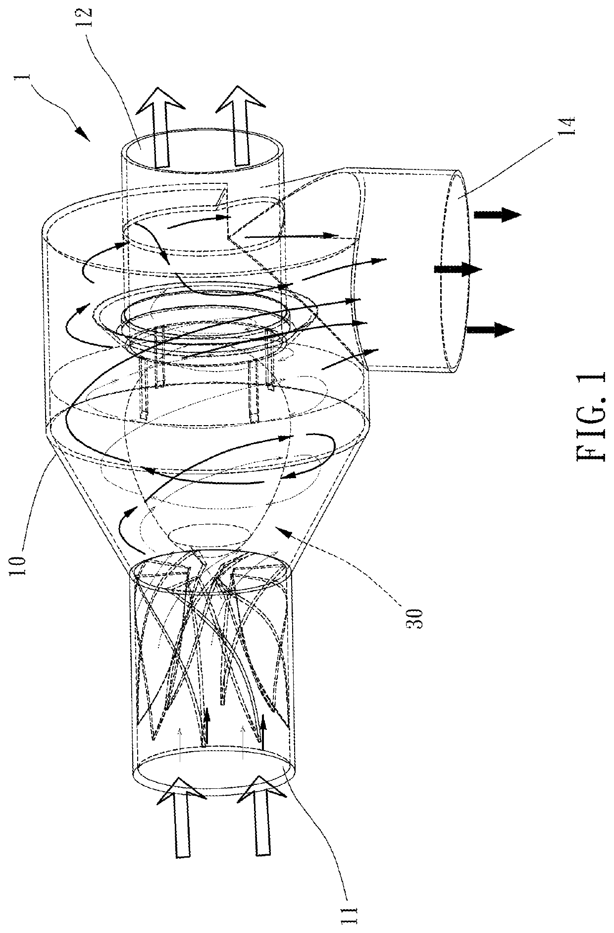
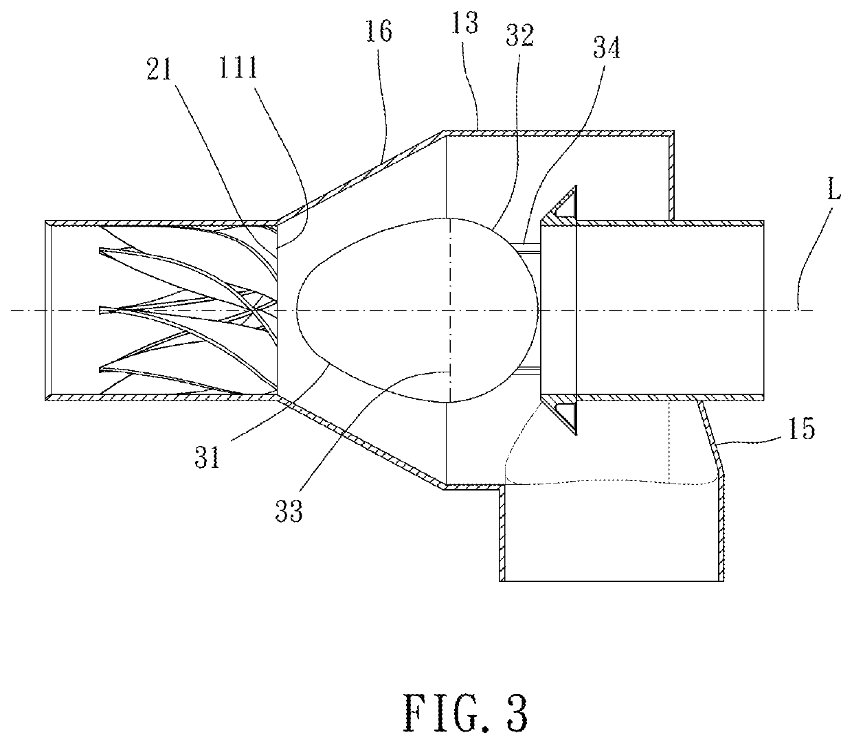
[0015]Please refer to FIGS. 1 to 8 for a preferable embodiment of the present invention. A centrifugal filtration device 1 of the present invention includes a casing 10, a plurality of blades 20 and a guiding mechanism 30.

[0016]The casing 10 includes an inlet passage 11 and an outlet passage 12 which are arranged along an extension direction L. The plurality of blades 20, relative to the extension direction L, extend spirally on an inner circumferential wall of the inlet passage 11. The guiding mechanism 30 includes a first tapering portion 31 tapered in a direction toward the inlet passage 11. The guiding mechanism 30 is disposed in the casing 10 and located between the plurality of blades 20 and the outlet passage 12. Therefore, the centrifugal filtration device 1 can form swirly flow and has high separation efficiency. Preferably, the casing 10, the inlet passage 11, the outlet passage 12 and the first tapering portion 31 each have a circular cross section so that the centrifugal...


PUM

PropertyMeasurementUnit
distanceaaaaaaaaaa
distanceaaaaaaaaaa
distanceaaaaaaaaaa

Abstract

A centrifugal filtration device is provided, including: a casing, including an inlet passage and an outlet passage which are arranged on an extension direction; a plurality of blades, extending spirally on an inner circumferential wall of the inlet passage relative to the extension direction; a guiding mechanism, including a first tapering portion tapered in a direction toward the inlet passage, disposed in the casing and located between the plurality of blades and the outlet passage.

Description

BACKGROUND OF THE INVENTIONField of the Invention[0001]The present invention relates to a centrifugal filtration device.Description of the Prior Art[0002]Generally, for separating particles with different sizes or processing particle-containing gas, the particle-containing gas is swirled to separate particles and gas by centrifugal force. Therefore, a conventional filtration device has a cylindrical housing and a guiding mechanism disposed in the housing for swirling the particle-containing gas. The filtration efficiency to the particle-containing gas depends on the structure of the guiding mechanism and its cooperation with the housing. However, the conventional filtration device has a poor configuration of the housing and the guiding mechanism, which results in collision and friction between the particle-containing gas and the filtration device so that the conventional filtration device cannot effectively utilize swirly flow to separate the particles and the gas and has poor filtr...

Claims


Application Information

Patent Timeline
Patent Type & Authority Patents(United States)
IPC IPC(8): B01D45/08B04C5/103B01D45/16B04C5/04F22B37/26F01K7/22F22B37/28F22B37/30
CPCB04C5/103B01D45/08B01D45/16B04C5/04F01K7/22F22B37/26F22B37/28F22B37/30B04C3/00B04C3/06
Inventor SON, JEONG HWA
Owner SON JEONG HWA
Why Eureka
Try Eureka