Separation device

a separation device and separation technology, applied in the direction of sedimentation settling tanks, separation processes, borehole/well accessories, etc., can solve the problems of high energy consumption of traditional dewatering devices, complex sewage post-treatment process, and high content of oil in discharged water, and achieve the effect of high separation efficiency

Active Publication Date: 2020-02-18
CHINA PETROCHEMICAL CORP +1
View PDF12 Cites 0 Cited by
  • Summary
  • Abstract
  • Description
  • Claims
  • Application Information

AI Technical Summary

Benefits of technology

[0006]The present invention aims at providing a separation device with higher separation efficiency. In particular, the present invention aims at providing a device for performing phase separation on the oilfield produced liquid.

Problems solved by technology

However, the traditional dewatering device has the shortcomings of high energy consumption, low efficiency, high content of oil in the discharged water, and complex sewage post-treatment process.
However, the oil content in the discharged water from such device for separating oil, water and solids is still greater than 500 mg / L, and only about 80% mud is separated out from the produced liquid, thereby requiring a very complex sewage post-treatment system.
Therefore, such device for separating oil, water and solids cannot satisfy the requirements of oilfield produced liquid containing a high content of moisture on efficient treatment of a large amount of liquid.

Method used


Image

  • Separation device
  • Separation device

Examples


example 1

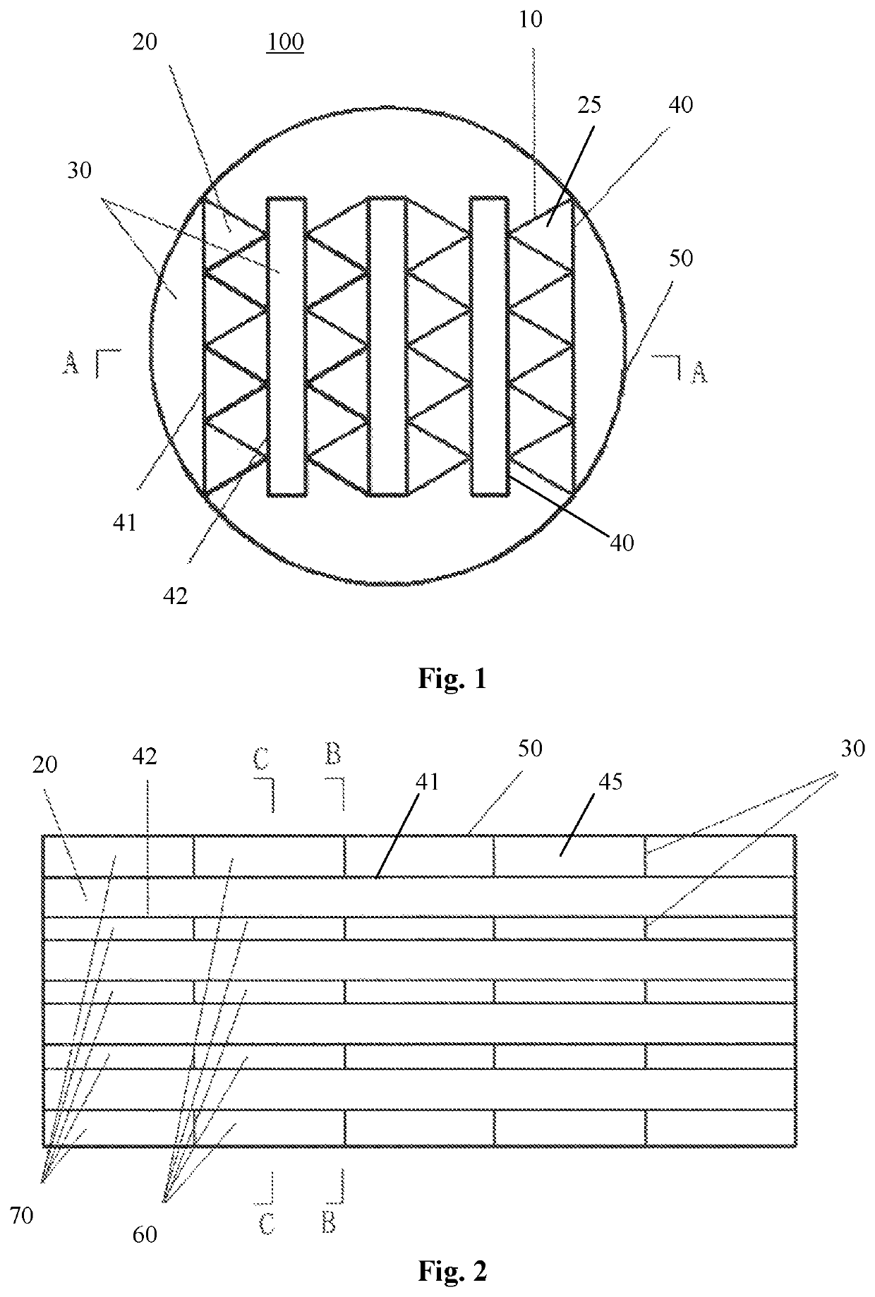
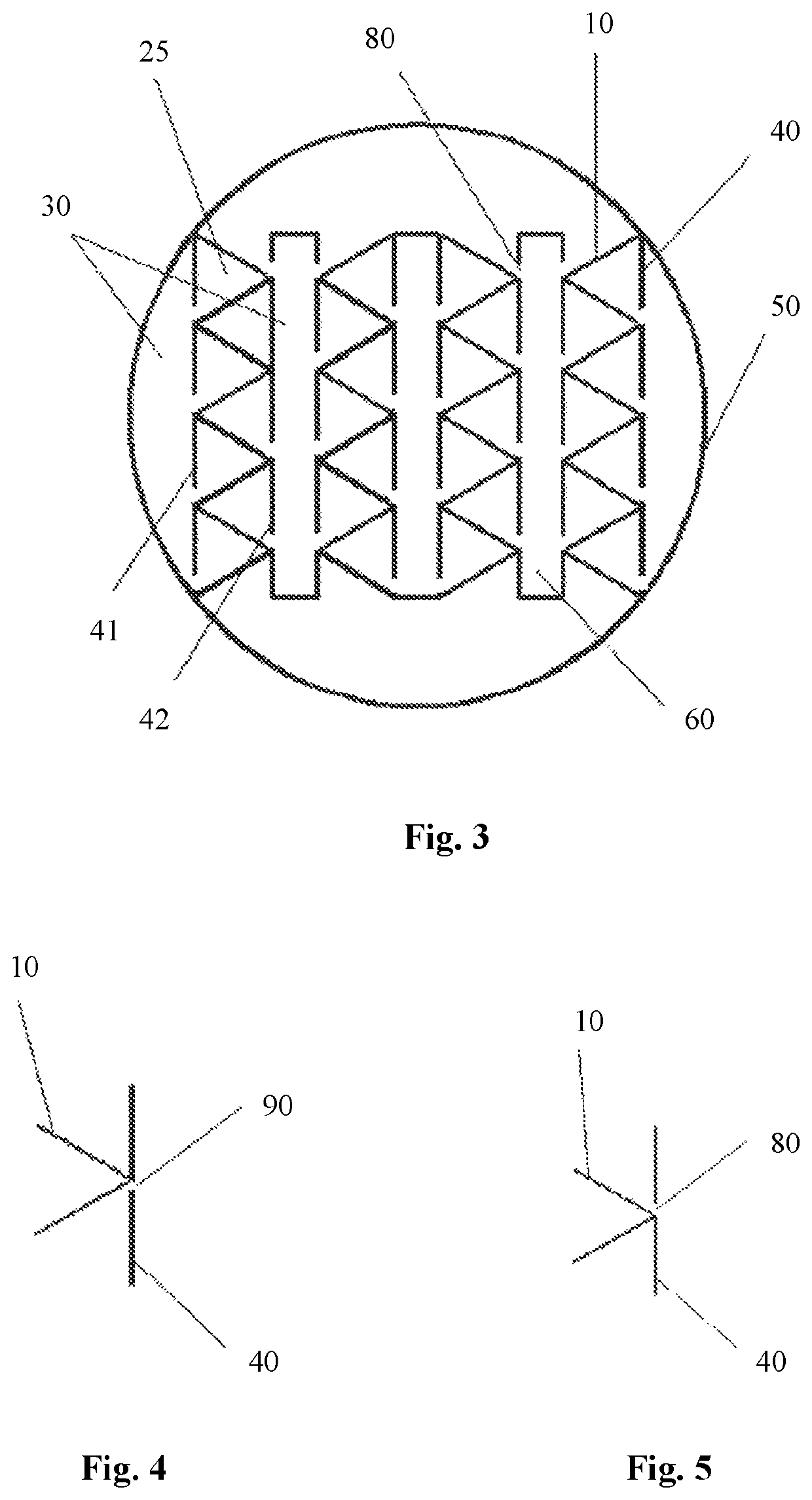
[0047]The fluid phase separation device 100 as shown in FIG. 1 to FIG. 5 is utilized to perform phase separation on heavy oil produced liquid. The heavy oil produced liquid has a moisture content of 85%, with a crude oil density of 0.95 g / cm.

[0048]In the fluid phase separation device 100, a lateral baffle plate 10 is 2 m in length and 50 mm in width. The angle formed between the lateral baffle plate 10 and the longitudinal baffle plate 40 is 60 degrees. The collection chamber 45 is 50 mm in width. The diameter of the oil phase guiding hole 80 is 3 mm, and the diameter of the suspended solid phase guiding hole 90 is 20 mm.

[0049]Experiments show that, when the fluid phase separation device 100 is utilized to treat the above heavy oil produced liquid, the oil phase fluid as separated has a moisture content of 21%, and the aqueous phase fluid as separated has an average oil content of 22 mg / L and an average suspended solid content of 14 mg / L. The water quality of the aqueous phase can s...

example 2

[0050]The fluid phase separation device 100 as shown in FIG. 1 to FIG. 5 is utilized to perform phase separations on heavy oil produced liquid. The heavy oil produced liquid has a moisture content of 85%, with a crude oil density of 0.95 g / cm3.

[0051]In the fluid phase separation device 100, a lateral baffle plate 10 is 3 m in length and 81 mm in width. The angle formed between the lateral baffle plate 10 and the longitudinal baffle plate 40 is 67.5 degrees. The collection chamber 45 is 80 mm in width. The diameter of the oil phase guiding hole 80 is 4 mm, and the diameter of the suspended solid phase guiding hole 90 is 30 mm.

[0052]Experiments show that, when the fluid phase separation device 100 is utilized to treat the above heavy oil produced liquid, the oil phase fluid as separated has a moisture content of 28%, the aqueous phase fluid as separated has an average oil content of 28 mg / L and an average suspended solid content of 13 mg / L. The water quality of the aqueous phase can s...


PUM

PropertyMeasurementUnit
angleaaaaaaaaaa
angleaaaaaaaaaa
lengthaaaaaaaaaa

Abstract

Disclosed herewith a separation device for performing phase separation on a three-phase liquid. The device includes: a housing; at least one pair of longitudinal baffle plates; a flow channel formed between every pair of longitudinal baffle plates; and collection chambers formed between adjacent pairs of longitudinal baffle plates. Each collection chamber is provided with a transverse baffle plate to separate the collection chamber into a first phase and a second phase collection cells. Each flow channel is provided with multiple lateral baffle plates to separate the flow channel into multiple sub-channels. In the areas of each longitudinal baffle plate where the first phase and second phase collection cells are located respectively, said longitudinal baffle plate is provided with a first and a second phase guiding holes in communication with the first phase and the second collection cells respectively.

Description

TECHNICAL FIELD[0001]The present invention relates to a separation device, in particular to a device configured to separate various phases from a three-phase mixture. Particularly, the present invention relates to a device for separating oilfield produced liquid.BACKGROUND ART[0002]It is a commonly used technology in modern industries to separate various phases from a mixture containing multiple phases, and the technology has been widely used in multiple fields. For example, in municipal sewage treatment and industrial sewage treatment, the sewage containing oil and suspended solids needs to be separated, so as to perform classified treatment afterwards.[0003]In addition, in the oil extraction industry, it is even an important technology to perform phase separation on the oilfield produced liquid. The oilfield produced liquid is complex in components, but it can usually be deemed as a three-phase mixture which mainly contains three phases, including water, oil and suspended solids.[...

Claims


Application Information

Patent Timeline
Patent Type & Authority Patents(United States)
IPC IPC(8): B01D17/028B01D17/02B01D21/00B01D21/02E21B43/34
CPCB01D21/0087B01D21/0051E21B43/34B01D17/0211B01D17/0214B01D21/0039B01D17/02B01D21/02E21B43/35
Inventor HU, CHANGCHAODANG, WEIXU, XIAOXUANTANG, ZHIWEIWANG, LILITAN, WENJIEDING, PENGYUANBI, CAIXIAZHENG, YOULIN
Owner CHINA PETROCHEMICAL CORP
Why Eureka
Try Eureka