Robotic Partial Pallet Product Lifting System

a robotic and partial pallet technology, applied in the direction of de-stacking articles, thin material handling, article separation, etc., can solve the problems of the entire product layer falling out of the grasp of the picking device, time-consuming and laborious to manually organize and prepare individual orders, etc., to improve the picking effect of products

Inactive Publication Date: 2010-01-21
HENDERSON TOBY D
View PDF11 Cites 26 Cited by
  • Summary
  • Abstract
  • Description
  • Claims
  • Application Information

AI Technical Summary

Benefits of technology

[0016]In another implementation of the end-effector or robotic system, the end-effector may include a vacuum pad assembly for providing suction or vacuum grasping capabilities to the end-effector. The vacuum pad assembly provides a suction force to grasp the tops of products forming the top layer of products on a pallet. This vacuum grasping allows for improved picking of products that have odd shapes that would normally become loose if merely grasped by providing lateral loading forces by clamping plates.

Problems solved by technology

Unfortunately, it can be very time consuming and labor intensive to manually organize and prepare the individual orders for each of the different retail establishments.
Unfortunately, the configuration of the packaging for many items prevents good pressing of the various adjacent rows into one another resulting in loose items in the layer.
The loose items will fall out of the layer when lifted by the picking device creating instability in the pressure which will ultimately result in the entire layer of product falling out from the grasp of the picking device.
Further yet, prior picking devices typically could only pick full layers of items.
Unfortunately, if a retailer only wanted a partial layer of items, the picking device could not be used for such selection of items.
For example, if a retailer only wanted 15 cases of one type of beverage from a pallet identified above, the picking device could not fill that order because the picking device could not get between the various rows to only take 3 rows of cases.

Method used


Image

  • Robotic Partial Pallet Product Lifting System
  • Robotic Partial Pallet Product Lifting System
  • Robotic Partial Pallet Product Lifting System

Examples


Embodiment Construction

[0029]While embodiments of the invention may be described in relation to moving products in the beverage industry, the present invention finds utility and applicability in product distribution centers distributing any type of product, beyond beverages.

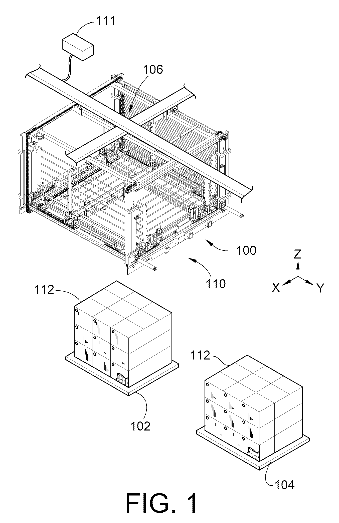
[0030]FIG. 1 is a simplified perspective illustration of a robotic system 100 for automatically loading and unloading pallets 102, 104. The robotic system 100 includes gantry system 106 for positioning an end-effector 110 in three dimensions along an x-axis, y-axis and z-axis that are preferably orthogonal to one another. The robotic system 100 further includes a controller 111 for controlling the movement and operations of the end-effector 110 and gantry system 106. While the end-effector 110 is coupled to a gantry system 106, other robotic systems can be used to control the position of the end-effector 110. For example, a pedestal robot could be used to support and position end-effector 110. More particularly, a 5-axis or 6-axis pede...


PUM


Abstract

A robotic gantry system, end-effector for a robotic gantry system and method of transporting products using a robotic gantry system is provided. The end-effector includes a movable floor that can be positioned below picked products to prevent products from being dropped during transport. The movable floor also permits selecting individual rows of products from a given layer of products of a product stack. The end-effector may include a vacuum assembly for vacuum adhering to the products. The method permits selection of varying portions of a stack of products with the end-effector and protecting the selected portions of products using the movable floor.

Description

CROSS-REFERENCE TO RELATED PATENT APPLICATIONS[0001]This patent application claims the benefit of U.S. Provisional Patent Application No. 61 / 081,412, filed Jul. 17, 2008, the disclosure and teachings of which are incorporated herein, in their entireties, by reference.FIELD OF THE INVENTION[0002]This invention generally relates to product distribution systems and more particularly product distribution systems within a warehouse.BACKGROUND OF THE INVENTION[0003]In today's market place, retail goods are often mass produced then shipped in bulk to central warehouses prior to being distributed to individual local retail establishments.[0004]The retail goods may be shipped in bulk on large pallets to the central warehouses. For example, a pallet of numerous cases of individual products such as, for example, bottles or cans of beverages. The cases will be stacked in several layers on the pallets. For example, a pallet of cases may include a single layer of cases that is five cases wide alo...

Claims


Application Information

Patent Timeline
Patent Type & Authority Applications(United States)
IPC IPC(8): B65G59/00
CPCB65G61/00B65G57/24
Inventor HENDERSON, TOBY D.
Owner HENDERSON TOBY D
Why Eureka
Try Eureka