Wireless transfer of information using magneto-electric devices

a technology of magnetoelectric devices and wireless communication, applied in the direction of transmission, near-field transmission, electric devices, etc., can solve the problems of difficult detection of inability to communicate information wirelessly over a small distance, and inability to detect such a small magnetic field

Inactive Publication Date: 2010-01-21
FERRO SOLUTIONS
View PDF11 Cites 292 Cited by
  • Summary
  • Abstract
  • Description
  • Claims
  • Application Information

AI Technical Summary

Benefits of technology

[0030]The electro-active component may be of a hard, high Q piezoelectric material.

Problems solved by technology

However, communicating information wirelessly over modest distances (from a few cm up to several meters or even a few km) has remained problematic for a variety of reasons.
However, it is known that inductive coupling becomes increasingly less efficient as the size of the induction coils decreases.
Propagating radio-frequency (RF) EM waves face challenges in circumstances such as underground communications and communication in and around large build structures due to dielectric absorption and metallic shielding.
Absorption of RF waves by moisture and body tissue also present problems for this technology.
Another challenge facing any high-frequency EM signal for ground penetration or through-building communication, is the skin effect.
To detect such a small magnetic field is a challenge.
However, for long distance NFMC, a few inherent drawbacks limit its performance.
Operation at higher frequency brings problems for ground penetration of the magnetic field; low frequency gives better performance.
Second, induction coils require many electrical turns to achieve high magnetic sensitivity; this adds resistivity, which increases electrical loss and reduces the device quality factor, Q. Lastly, the performance of a pick-up coil scales with its volume5 / 3, so receive coils lose efficiency rapidly with decreasing size.

Method used


Image

  • Wireless transfer of information using magneto-electric devices
  • Wireless transfer of information using magneto-electric devices
  • Wireless transfer of information using magneto-electric devices

Examples


Embodiment Construction

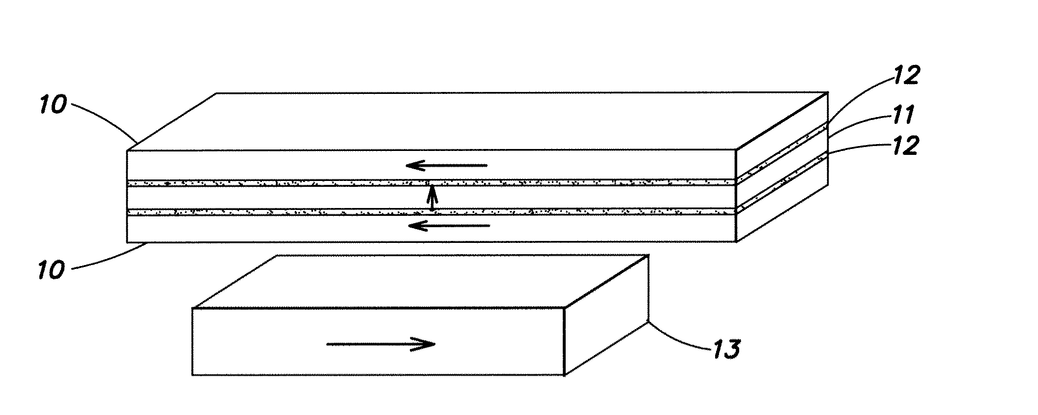
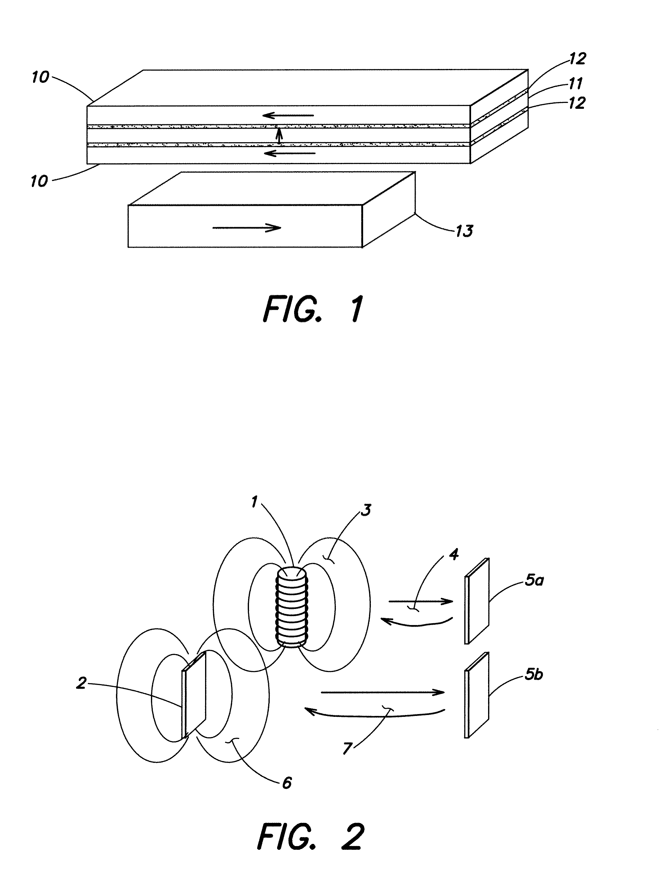
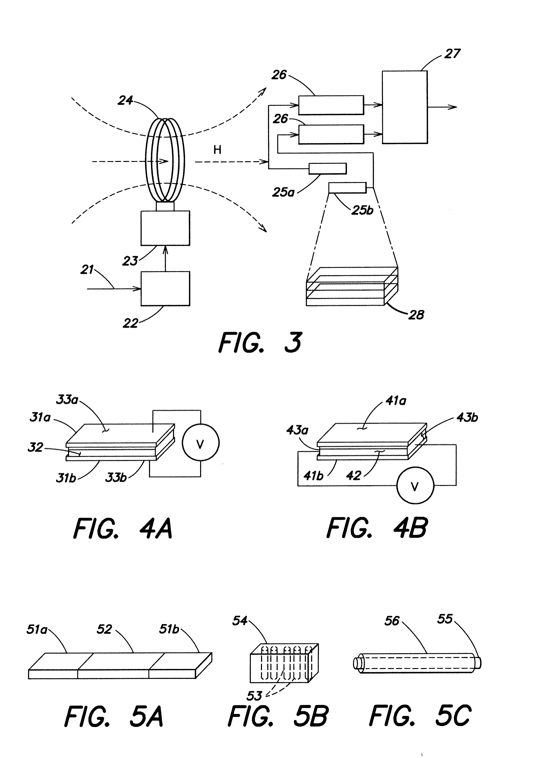
[0055]Various embodiments will now be described for the wireless transmission of analog or digital information (e.g., voice or data) and optional power transfer accomplished with a system that includes ME receiver(s) and either coil or ME transmitter(s), plus electronics to power the transmitter and modulation and demodulation circuits to imprint information to the carrier wave and retrieve the information from it. The information may be any signal in analog or digital form and includes but is not limited to text, voice, graphics, video or other data.

[0056]While radio frequency (RF) communication has achieved great success over the past few decades, it still faces challenges in circumstances such as underground communications and or reception through large build structures due to dielectric absorption and metallic shielding. Near-field magnetic communication (NFMC), on the other hand, is very well suited for those environments. So far NFMC has been achieved through coil-to coil indu...


PUM


Abstract

Apparatus and method for wireless near-field magnetic communication (NFMC) of information (e.g., voice or data) over modest distances (centimeters to a few kilometers). The transmission can proceed from an inductive coil transmitter to a magneto-electric (ME) receiving device, or between two ME devices. Electrical power may also be transmitted from and/or received using the same device. In one case, power and data are transmitted from an induction coil to a distant ME device that collects power and transmits data back to the power-transmission coil. In another case, the wireless transfer of data can be carried out between two ME devices. ME devices can be engineered to transmit or receive data and to receive electric power over a variety of frequencies by changing their dimensions, their material makeup and configuration, electrode configurations, and/or their resonance modes (longitudinal, transversal, bending, shear etc). Data rates up to and above several kilo-bits/s are possible using these methods with no limits on the frequency and duration of the communication.

Description

RELATED APPLICATIONS[0001]This application claims the benefit of and incorporates by reference in its entirety U.S. Provisional Application 61 / 135,295 filed 18 Jul. 2008.BACKGROUND[0002]There are growing needs for short-range, wireless communications in a number of diverse fields including but not limited to radio frequency identification (RFID), secure intra-person data transfer, implanted medical therapies and health monitoring, and collecting data from inaccessible sensors. However, communicating information wirelessly over modest distances (from a few cm up to several meters or even a few km) has remained problematic for a variety of reasons.[0003]For two centuries voice and data have been transmitted via electromagnetic (EM) waves, either guided between a telegraph line and ground or propagating in the atmosphere on radio waves. Concurrently, electrical power has been transformed by electromagnetic (EM) devices (generators and motors). The transmitters of these technologies are...

Claims


Application Information

Patent Timeline
Patent Type & Authority Applications(United States)
IPC IPC(8): H04B5/00
CPCH04B5/00H04B5/0075H04B5/0037H04B5/0031
Inventor LIU, YIMINGSIMON, JESSEO'HANDLEY, ROBERT C.HUANG, JIANKANG
Owner FERRO SOLUTIONS
Why Eureka
Try Eureka