Method for determining faulty components in a system

a technology of faulty components and systems, applied in the direction of testing/monitoring control systems, instruments, nuclear elements, etc., can solve the problem of insufficient evaluation of a single corresponding symptom

Inactive Publication Date: 2010-01-21
ROBERT BOSCH GMBH
View PDF3 Cites 34 Cited by
  • Summary
  • Abstract
  • Description
  • Claims
  • Application Information

AI Technical Summary

Benefits of technology

[0010]In a still further variant of the method, in particular in the event that a vehicle is evaluated as a system, the readout of system or vehicle data takes place, which include sensor data of the components. When setting up at least one of the lists, it is also possible to take externally input symptom data, e.g., defects described by the driver or errors of the vehicle during operation, into account. Furthermore, a control device of the system, e.g., an engine control, may take vehicle data into account that is output at a corresponding data bus.
[0011]Moreover, the present invention relates to a computer program product, which induces the implementation of a corresponding method on a program-controlled computing or control device. For instance, a PC or a computer for the control of a vehicle diagnosis system in service facilities, on which corresponding software or a computer program product is installed, may be used as program-controlled computing or control device. The computer-program product may be implemented in the manner of a data carrier such as, for example, a USB stick, floppy disk, CD-ROM, DVD, or also on a server device as a program file able to be downloaded.

Problems solved by technology

As a rule, the evaluation of a single corresponding symptom will be insufficient for determining the causal components in a complex error diagnosis.

Method used


Image

  • Method for determining faulty components in a system
  • Method for determining faulty components in a system
  • Method for determining faulty components in a system

Examples


Embodiment Construction

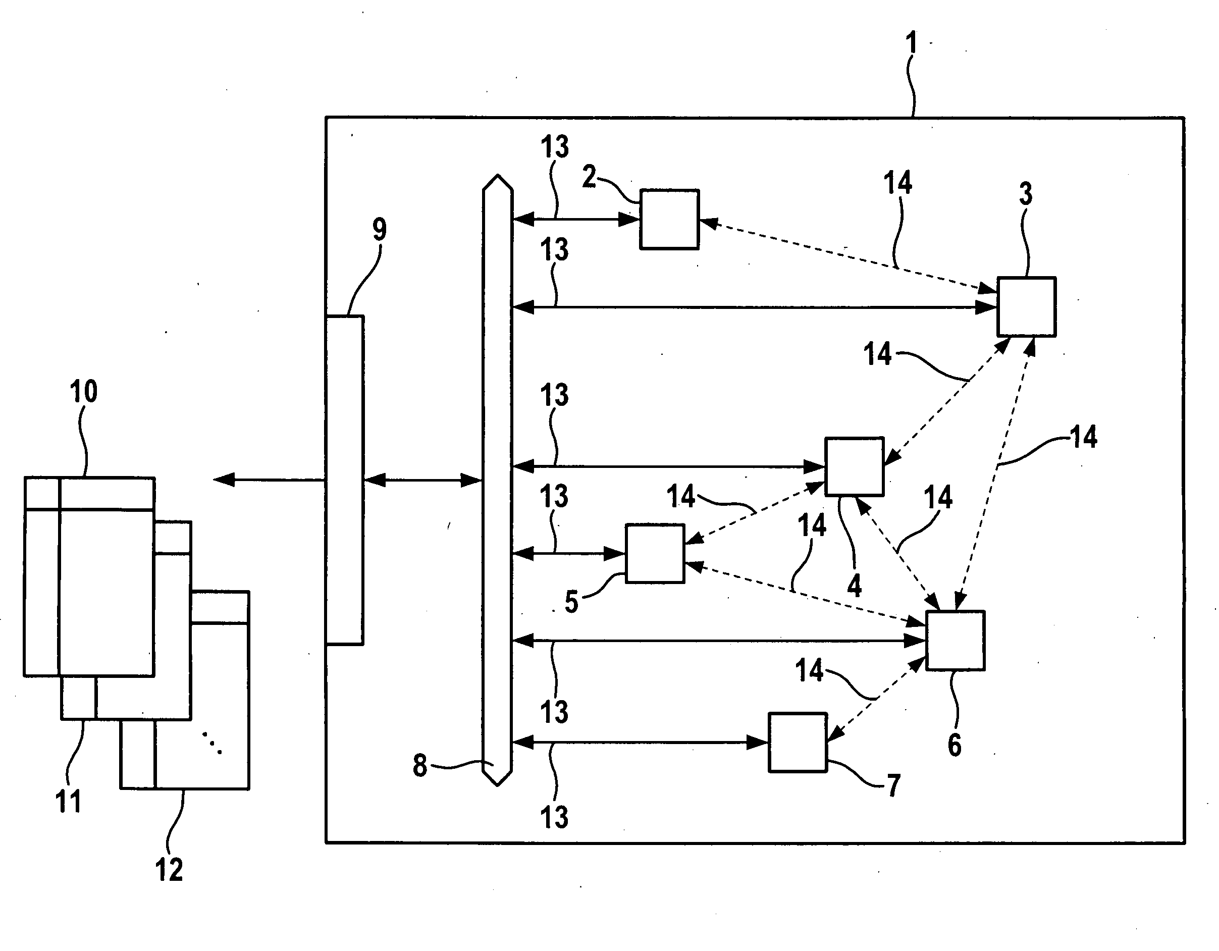
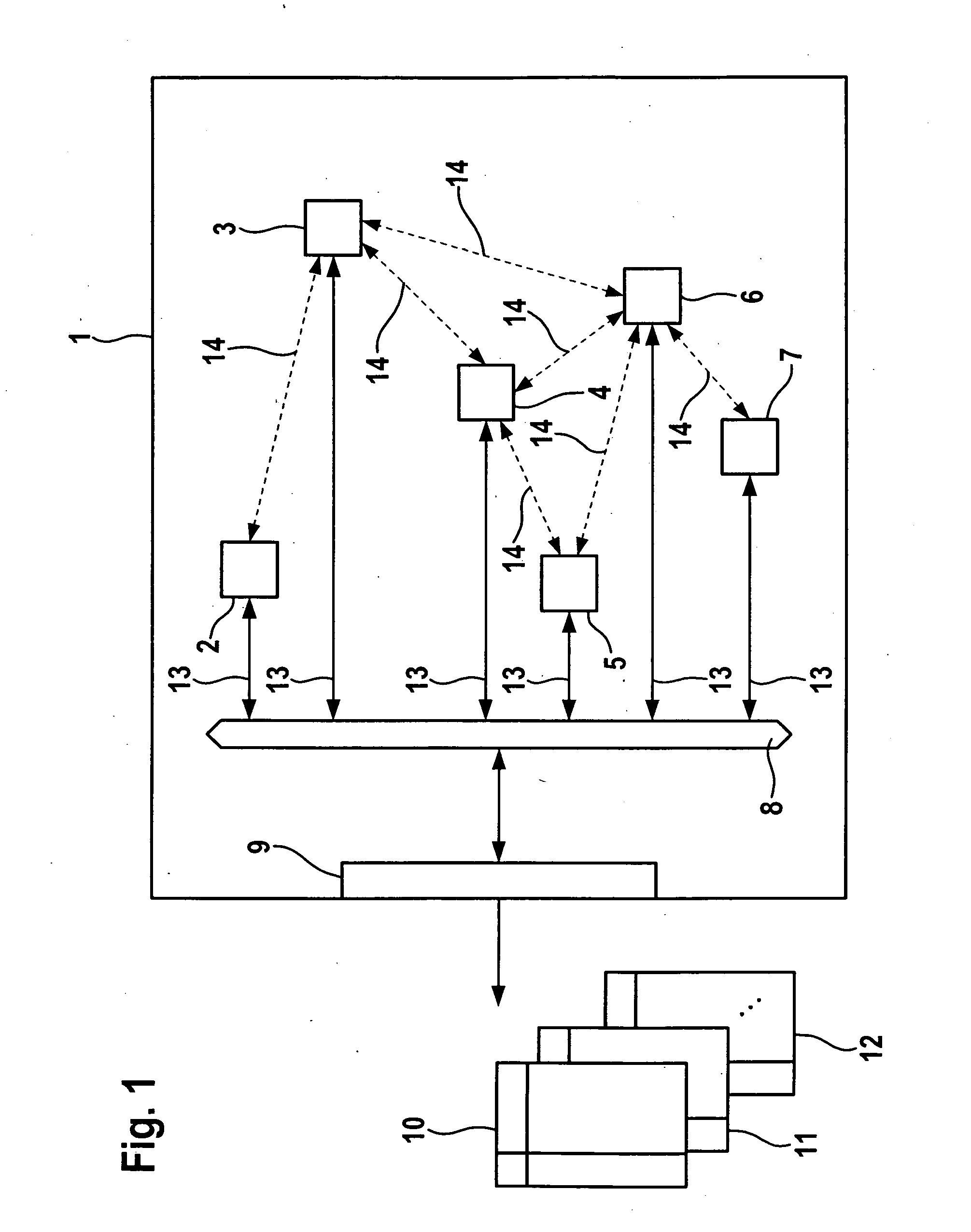
[0016]FIG. 1 schematically illustrates a system having a plurality of components. The system, e.g., a motor vehicle 1, is made up of a plurality of devices 2, 3, 4, 5, 5, 7, which may have an at least partial reciprocal effect on each other. This is indicated by arrows 14. Quite generally, system 1 may include components or devices 2 through 7, which, in merely exemplary fashion in connection with vehicles, may be components such as a coolant temperature sensor 2, an ignition control 3, a gasoline or fuel injection control system 4, a vehicle immobilizer 5, a fuel pump 6, and a fuel tank fill sensor 7.

[0017]In modern vehicles or systems, the various components 2 through 7 are coupled to an internal vehicle bus 8, as indicated by arrows 13 in FIG. 1. An example of an interaction or a mutual dependency of components 2 through 7 is that if the tank holds insufficient fuel, which is able to be detected by sensor 7, a fuel pump 6 will be unable to deliver fuel in coordination with fuel i...


PUM


Abstract

In a method for determining faulty components in a system having a plurality of interacting components, lists of potentially faulty components are prepared as a function of different diagnosis algorithms implemented independently of each other, and an error value is assigned to each potentially faulty component. The error values for at least one selection of components of the system are linked to form an error score value for a particular potentially faulty component.

Description

BACKGROUND OF THE INVENTION[0001]1. Field of the Invention[0002]The present invention relates to a method and a device for determining faulty components in a system, e.g., as it is required in an error diagnosis for a motor vehicle by a service facility.[0003]2. Description of Related Art[0004]In complex systems, which are made up of many components or devices as in the case of current motor vehicles, for example, the error search in the event of operating malfunctions, e.g., in a breakdown or during servicing to be carried out at regular intervals, takes place at the service station, usually by diagnostic systems. To this end, sensor data or historical information of the driving operation are read out and evaluated. For example, if a defect has occurred, then the most likely error cause, e.g., the malfunction of a specific component or device in the vehicle, is determined on the basis of the read-out data. Score tables, for instance, are used for this purpose, or the read-out vehic...

Claims


Application Information

Patent Timeline
Patent Type & Authority Applications(United States)
IPC IPC(8): G06F15/00
CPCG05B23/0251
Inventor DUC, NGHIA DANGENGEL, PETER
Owner ROBERT BOSCH GMBH
Why Eureka
Try Eureka