Leakage current detection and interruption circuit powered by leakage current

a leakage current and interruption circuit technology, applied in the direction of emergency protection detection, electrical equipment, fault current resposes, etc., can solve the problems of ground fault on the span, short circuit between the ac input terminals of the gfci, and disconnection of the protected motor

Inactive Publication Date: 2010-01-28
TECH RES
View PDF70 Cites 36 Cited by
  • Summary
  • Abstract
  • Description
  • Claims
  • Application Information

AI Technical Summary

Benefits of technology

[0038]The present invention is defined by the appended claims with specific embodiments being shown in the attached drawings. For the purpose of summarizing the invention, the invention comprises a circuit for disconnecting a power source upon the detection of a leakage current from one of a first and a second wire connected to the power source. The circuit comprises a sensing conductor located adjacent to one of the first and second wires for sensing a leakage current from one of the first and second wires. A disconnect switch is interposed within the first and second wires connected to the power source. A disconnect switch control circuit is connected to the sensing conductor for opening the disconnect switch solely from the leakage current from the sensing conductor.

Problems solved by technology

As a result a relay connected to the collector of the transistor is triggered, changing the state of its contacts and causing disconnection of the protected motor.
In case closing of the primary test switch contacts fails to trip the GFCI, subsequent closing of the secondary test switch contacts results in a short circuit between the AC input terminals of the GFCI.
If the earth ground pin has been properly connected to earth ground, applying the conductive path will place a ground fault on the span, which is detected by a ground fault detector within the central office line card.

Method used


Image

  • Leakage current detection and interruption circuit powered by leakage current
  • Leakage current detection and interruption circuit powered by leakage current
  • Leakage current detection and interruption circuit powered by leakage current

Examples


first embodiment

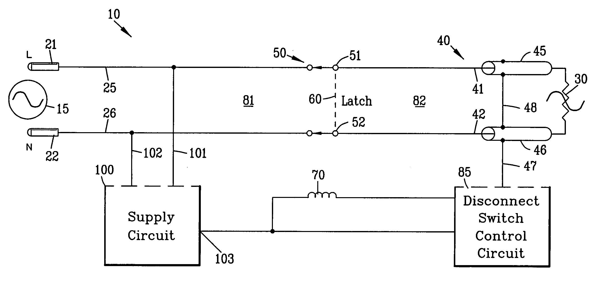
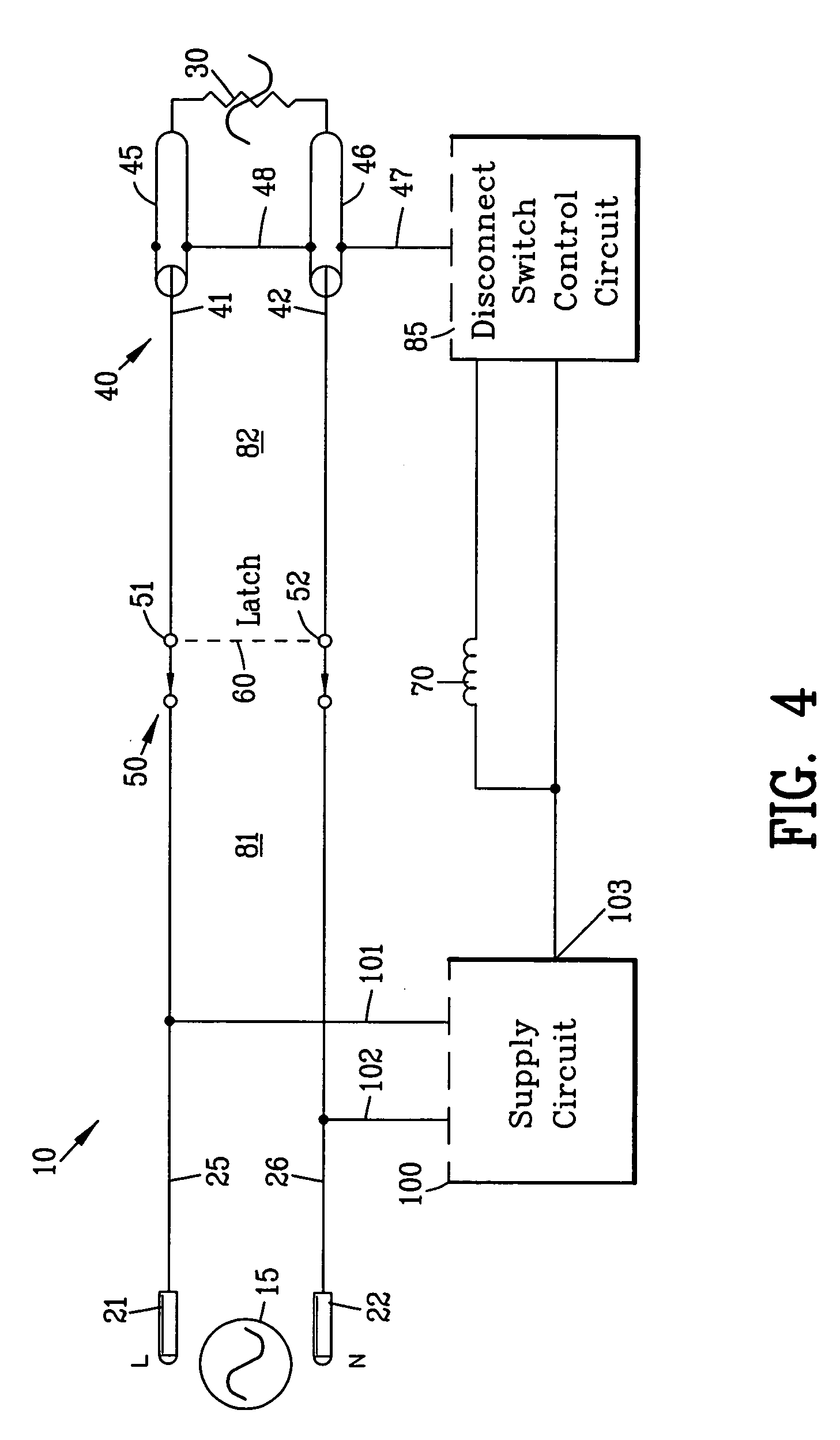
[0080]FIG. 4 is a block diagram of the present invention illustrating a circuit 10 for disconnecting an electrical power source 15 from the load 30 upon the detection of a leakage current within the wire assembly 40. In this example, the electrical power source 15 is shown as a conventional 120 volt alternating current (AC) power source. The first terminal 21 is the line terminal whereas the second terminal 22 is the neutral terminal. Although the electrical power source 15 has been shown as conventional 120 volt alternating current (AC) power source, it should be appreciated by those skilled in the art that the present invention may be adapted to virtually any type of power source.

[0081]The circuit 10 comprises a disconnect switch 50 interposed a first and a second terminal wires 25 and 26 and the first and second wires 41 and 42 for disconnecting the power source 15 from the load 30.

[0082]The disconnect switch 50 is shown as a normally open switch having a mechanical latch 60 for ...

second embodiment

[0096]FIG. 10 is a circuit diagram of a leakage detection and interruption circuit 10A of the present invention. In this embodiment, similar components are labeled with similar numbers in prior embodiments with a different alphabetical character. A primary circuit 81A is defined between the electrical power source 15A and the disconnect switch 50A whereas a secondary circuit 82A is defined between the disconnect switch 50A and the load 30A.

[0097]In this example, a single shield 44A surrounding both the first and second wires 41A and 42A functions as shield sensing conductors for sensing a leakage current between the one of the first and second wires 41A and 42A and the shield 44A.

[0098]The supply circuit 100A is connected to the first and second wires 41A and 42A by conductors 101A and 102A in the secondary circuit 82A defined between the disconnect switch 50A and the load 30A to provide a node 103A. The supply circuit 100A is shown as a divider circuit 104A comprising diodes 105A a...

third embodiment

[0113]FIG. 13 is a circuit diagram of a leakage detection and interruption circuit 10B of the present invention. In this embodiment, similar components are labeled with similar numbers found in prior embodiments with a different alphabetical character.

[0114]In this example, a single shield 44B surrounding both the first and second wires 41B and 42B functions as shield sensing conductors for sensing a leakage current between the one of the first and second wires 41B and 42B and the shield 44B.

[0115]The supply circuit 100B is connected to the first and second wires 41B and 42B by conductors 101B and 102B in the secondary circuit 82B defined between the disconnect switch 50B and the load 30B to provide a node 103B. The supply circuit 100B is shown as a divider circuit 104B comprising diodes 105B and 106B to provide the node 103B.

[0116]The disconnect switch control circuit 85B is interposed between the shield 44B and the node 103B of the divider circuit 104B. In this embodiment, the dis...


PUM


Abstract

A circuit is disclosed for disconnecting a power source upon the detection of a leakage current from one of a first and a second wire connected to the power source. A sensing conductor is located adjacent to one of the first and second wires for sensing a leakage current from one of the first and second wires. A disconnect switch is interposed within the first and second wires connected to the power source. A disconnect switch control circuit is connected to the sensing conductor for opening the disconnect switch upon the presence of a leakage current from the sensing conductor. The disconnect switch control circuit operates solely from the leakage current from the sensing conductor.

Description

CROSS-REFERENCE TO RELATED APPLICATIONS[0001]This application claims benefit of U.S. Patent Provisional application No. 61 / 135,989 filed Jul. 24, 2008. All subject matter set forth in provisional application 61 / 135,989 filed Jul. 24, 2008 is hereby incorporated by reference into the present application as if fully set forth herein.BACKGROUND OF THE INVENTION[0002]1. Field of the Invention[0003]This invention relates to electrical power circuits and more particularly to a circuit for disconnecting a power source upon the detection of a leakage current.[0004]2. Description of the Related Art[0005]Various types of electrical protective devices have been proposed by the prior art for reducing the possibility of dangerous electrical shocks as well as the possibility of electrical fires. One general class of prior art electrical protective devices is a commonly referred to as a ground fault circuit interrupter (GFCI). A ground fault circuit interrupter disconnects a power source upon the ...

Claims


Application Information

Patent Timeline
Patent Type & Authority Applications(United States)
IPC IPC(8): H02H3/02
CPCH02H3/16H02H1/0007
Inventor GANDOLFI, PAUL R.
Owner TECH RES
Why Eureka
Try Eureka