
Dial Plate with Diffuse Lighting

a dial plate and diffuser technology, applied in the field of motor vehicles, can solve the problems of lack of diffuse light provision in yoshida and ikarashi, and achieve the effect of reducing the number of dial plates

Inactive Publication Date: 2010-01-28
HONDA MOTOR CO LTD
View PDF14 Cites 18 Cited by
  • Summary
  • Abstract
  • Description
  • Claims
  • Application Information

AI Technical Summary

Benefits of technology

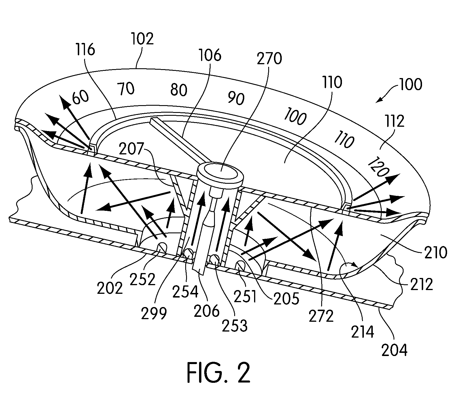
[0013]In another aspect, the light-guide includes an opaque portion configured to prevent light from escaping from at least one portion of the light-guide.

Problems solved by technology

Both Yoshida and Ikarashi lack provisions for providing diffuse light on an outer curved portion of a dial plate.

Method used


Image

  • Dial Plate with Diffuse Lighting
  • Dial Plate with Diffuse Lighting
  • Dial Plate with Diffuse Lighting

Examples


Embodiment Construction

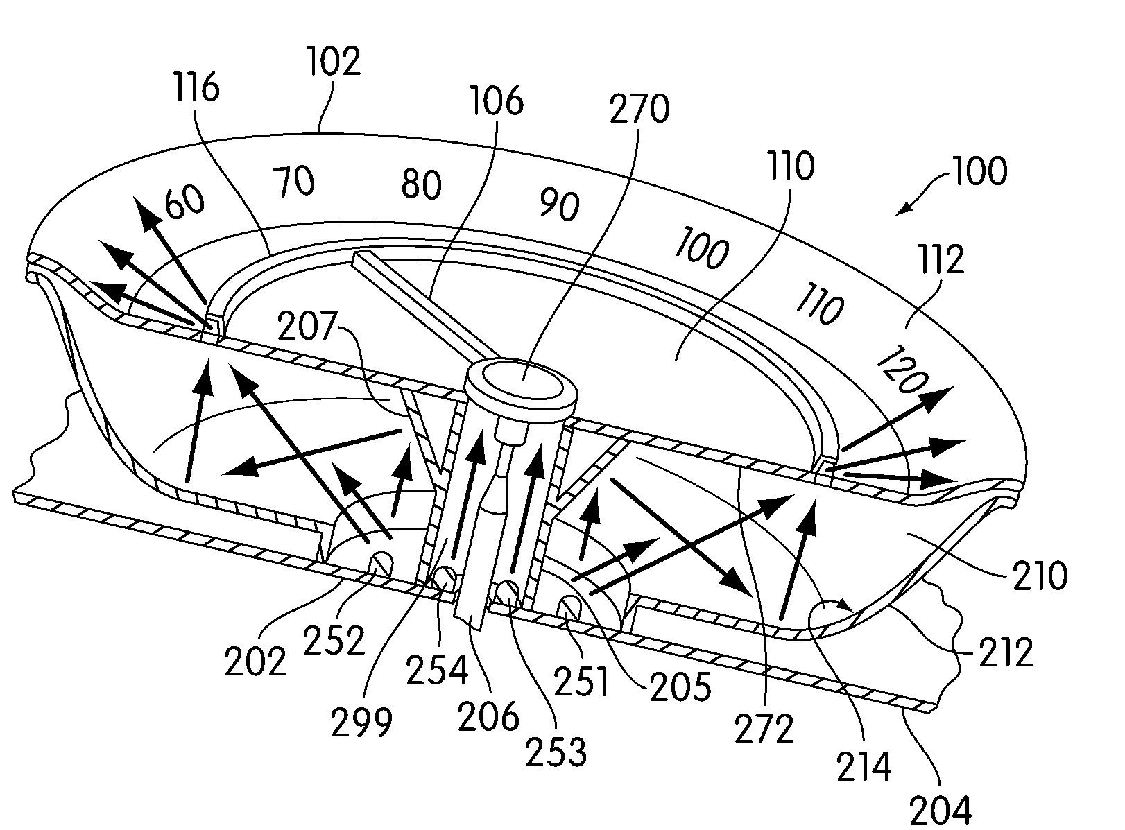
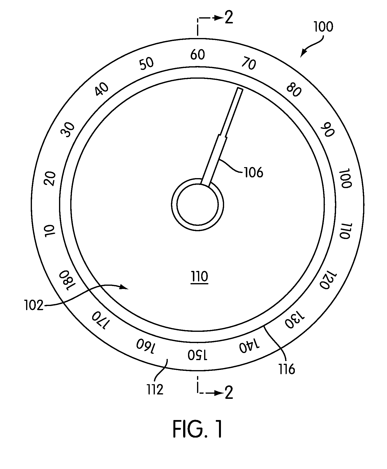
[0035]FIG. 1 is a front view of an embodiment of meter 100. Meter 100 may be associated with a motor vehicle of some kind. Generally, meter 100 could be associated with any type of motor vehicle, including, but not limited to, cars, trucks, vans, minivans, SUVs, motorcycles, scooters, boats, personal watercraft, and aircraft.

[0036]Generally, meter 100 may be placed in any location in a motor vehicle visible to a driver or passenger. In some embodiments, meter 100 may be disposed on a central console of a motor vehicle. In other embodiments, meter 100 may be disposed on a ceiling console of a motor vehicle. In an embodiment, meter 100 may be disposed on an instrument panel situated on a dashboard of a motor vehicle.

[0037]Generally, meter 100 may be any type of device configured to convey information to a driver or passenger. In some embodiments, meter 100 may be a tachometer. In other embodiments, meter 100 may be a fuel gauge. In the embodiment shown in FIG. 1, meter 100 is a speedo...


PUM


Abstract

A system for providing diffuse light to a dial plate of a meter is disclosed. The system includes a light-guide and a light source. The light from the light source enters the light-guide and exits the light-guide to illuminate a curved peripheral portion of a dial plate with a diffuse light.

Description

BACKGROUND OF THE INVENTION[0001]1. Field of the Invention[0002]The present invention relates to motor vehicles and in particular to a system for lighting a dial plate of a meter.[0003]2. Description of Related Art[0004]Lighting systems for lighting meters associated with a dashboard of a motor vehicle have been previously proposed. Yoshida et al. (Japanese Patent Number 60,239,605) is directed to a system for improving visibility of an indicator position. Yoshida teaches an indicating member disposed on the periphery of an indicating plate.[0005]Yoshida teaches a system including a light transmissible indicator that is associated with an indicating dial plate. Yoshida teaches that a greater part of the dial plate is flat, while an outside periphery includes an inclined part that is printed with characters. Light is emitted at a light source and transferred through a light-guiding plate. Yoshida teaches that light is only reflected onto the inclined part and the rest of the dial pla...

Claims


Application Information

Patent Timeline
IPC IPC(8): G01D11/28
CPCG01D11/28Y10S116/05B60K2360/336
Inventor FEIT, STEVEN
Owner HONDA MOTOR CO LTD
Learn More